Real-time blood pressure measuring device and method for measuring pulse wave transmission time difference in real time

A transmission time difference, real-time measurement technology, applied in the directions of diagnostic recording/measurement, sensor, blood vessel evaluation, etc., can solve the problems of measurement result error, complicated operation, and the corresponding relationship is not very clear, and achieve the effect of high accuracy

Active Publication Date: 2014-03-19
心永(深圳)科技有限公司
View PDF4 Cites 41 Cited by
  • Summary
  • Abstract
  • Description
  • Claims
  • Application Information

AI Technical Summary

Problems solved by technology

There are three shortcomings in this method of measurement: first, the measurement of ECG signals requires surface-attached electrodes in multiple places on the human body, which is complicated to operate and requires certain professional skills; second, the corresponding relationship between the R wave of the ECG signal and the pulse wave peak is not very clear. The calculated pulse wave transmission time needs to be corrected; third, the operation involves multiple parts of the human body. In actual application, not only the body needs to carry multiple ECG electrode connections, but also small changes in the measurement posture and the relative positions of each measurement point may cause problems. Changing the measured pulse wave transmission time will lead to certain errors in the measurement results

Method used


Image

  • Real-time blood pressure measuring device and method for measuring pulse wave transmission time difference in real time
  • Real-time blood pressure measuring device and method for measuring pulse wave transmission time difference in real time
  • Real-time blood pressure measuring device and method for measuring pulse wave transmission time difference in real time

Examples


Embodiment 1

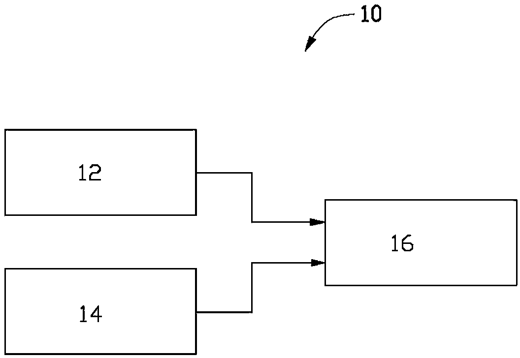
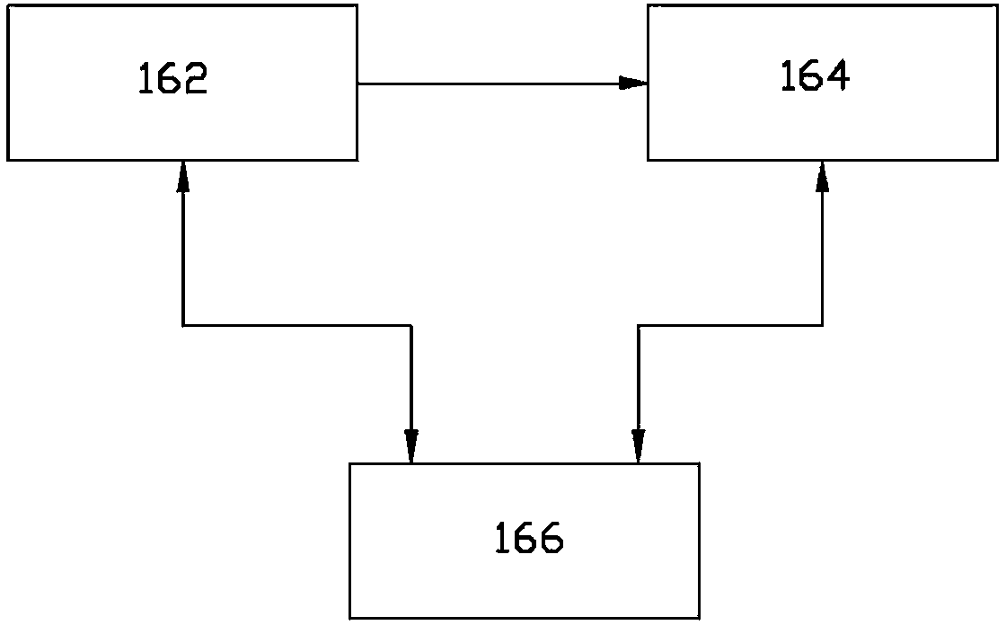
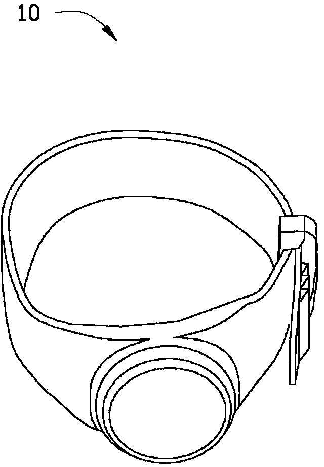
[0057] The blood pressure real-time measurement device 10 includes a first pulse wave sensing module 12, a second pulse wave sensing module 14, a signal processing module 16 and a wireless transmission module. The first pulse wave sensing module 12 , the second pulse wave sensing module 14 , the signal processing module 16 and the wireless transmission module are integrated on a flexible circuit board and form a wristband for real-time measurement of wrist radial artery blood pressure. Wherein, the first pulse wave sensing module 12 is a pressure pulse wave sensing module, and the second pulse wave sensing module 14 is a photoplethysmography sensing module.

[0058] see Figure 5 , Figure 5 is the measured pressure pulse wave signal and photoplethysmography pulse wave signal. The upper waveform is the pressure pulse wave, and the lower waveform is the photoplethysmographic pulse wave. Among them, in a certain cardiac cycle, the systolic pulse wave transit time difference P...

Embodiment 2

[0060] The blood pressure real-time measurement device of this embodiment is basically the same as the blood pressure real-time measurement device of Embodiment 1, the difference is that in this embodiment, the first pulse wave sensing module 12 is a blood flow velocity pulse wave sensing module, and the second pulse wave The sensing module 14 is a photoplethysmography sensing module.

[0061] see Image 6 , Image 6are the measured blood flow velocity pulse wave signal and photoplethysmography wave signal. The upper waveform is the blood flow velocity pulse wave, and the lower waveform is the photoplethysmographic pulse wave. Among them, in a certain cardiac cycle, the systolic pulse wave transit time difference PTTS is the time interval between the first peaks of the above two pulse waves (the interval between two solid lines), and the diastolic pulse wave transit time difference PTTD is the above two pulse wave The time interval between the first troughs (the interval be...

Embodiment 3

[0063] The blood pressure real-time measurement device of this embodiment is basically the same as the blood pressure real-time measurement device of Embodiment 1, the difference is that in this embodiment, the first pulse wave sensing module 12 is a blood flow velocity pulse wave sensing module, and the second pulse wave The sensing module 14 is a pressure pulse wave sensing module.

[0064] see Figure 7 , Figure 7 is the measured blood flow velocity pulse wave signal and pressure pulse wave signal. The upper waveform is the blood flow velocity pulse wave, and the lower waveform is the pressure pulse wave. Among them, in a certain cardiac cycle, the systolic pulse wave transit time difference PTTS is the time interval between the first peaks of the above two pulse waves (the interval between two solid lines), and the diastolic pulse wave transit time difference PTTD is the above two pulse wave The time interval between the second peaks (the interval between two dotted li...


PUM


Abstract

The invention relates to a real-time blood pressure measuring device. The real-time blood pressure measuring device comprises a first pulse wave sensing module, a second pulse wave sensing module and a signal processing module. The first pulse wave sensing module is used for obtaining a first pulse wave signal of every heartbeat cycle; the second pulse wave sensing module is used for obtaining a second pulse wave signal of every heartbeat cycle; the pulse waves obtained by the first pulse wave sensing module and the second pulse wave sensing module are different in types; the signal processing module is used for obtaining the same artery position, meanwhile, obtaining the transmission time difference between the first pulse wave signal and the second pulse wave signal and obtaining the artery blood pressure of every heartbeat cycle according to the transmission time difference.

Description

technical field [0001] The invention relates to a blood pressure measuring device and a method for measuring a pulse wave transit time difference, in particular to a blood pressure real-time measuring device and a real-time measuring method for a pulse wave transit time difference. Background technique [0002] Blood pressure is an important physiological parameter reflecting the function of the human circulatory system. Real-time measurement of blood pressure has great practical significance in medicine. First of all, the fluctuation curve of human blood pressure can reflect the relevant information of cardiovascular and cerebrovascular physiological state, and can be used as important reference data. For example, the real-time blood pressure of hypertensive patients directly reflects the patient's physical condition, so real-time blood pressure measurement can be used as an important monitoring method to ensure that hypertensive patients receive timely treatment in case o...

Claims


Application Information

Patent Timeline
Patent Type & Authority Applications(China)
IPC IPC(8): A61B5/021A61B5/0285
Inventor 邓宁李毅彬高扬宇张洋李申龙李洪阳
Owner 心永(深圳)科技有限公司
Why Eureka
Try Eureka