A cast iron anode mold for increasing the amount of copper poured and its production method

A production method and anode technology, applied in casting molds, casting mold components, casting molding equipment, etc., can solve problems such as improper material selection, unreasonable structural design, and short service life of cast iron anode molds, and achieve significant economic and social benefits , reduce the labor load and reduce the effect of internal stress

Active Publication Date: 2015-08-19
大冶有色机电设备修造有限公司
View PDF6 Cites 0 Cited by
  • Summary
  • Abstract
  • Description
  • Claims
  • Application Information

AI Technical Summary

Problems solved by technology

[0003] The purpose of the present invention is to solve the problems of improper material selection, unreasonable structural design, large internal stress during production, easy cracks, resulting in bursting and scrapping, short service life, and less copper pouring amount in the existing cast iron anode mold, and to provide a method to improve casting Copper weight cast iron anode mold and production method thereof

Method used


Image

  • A cast iron anode mold for increasing the amount of copper poured and its production method
  • A cast iron anode mold for increasing the amount of copper poured and its production method
  • A cast iron anode mold for increasing the amount of copper poured and its production method

Examples


example 1

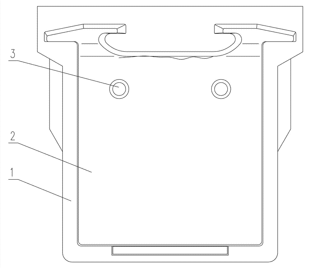
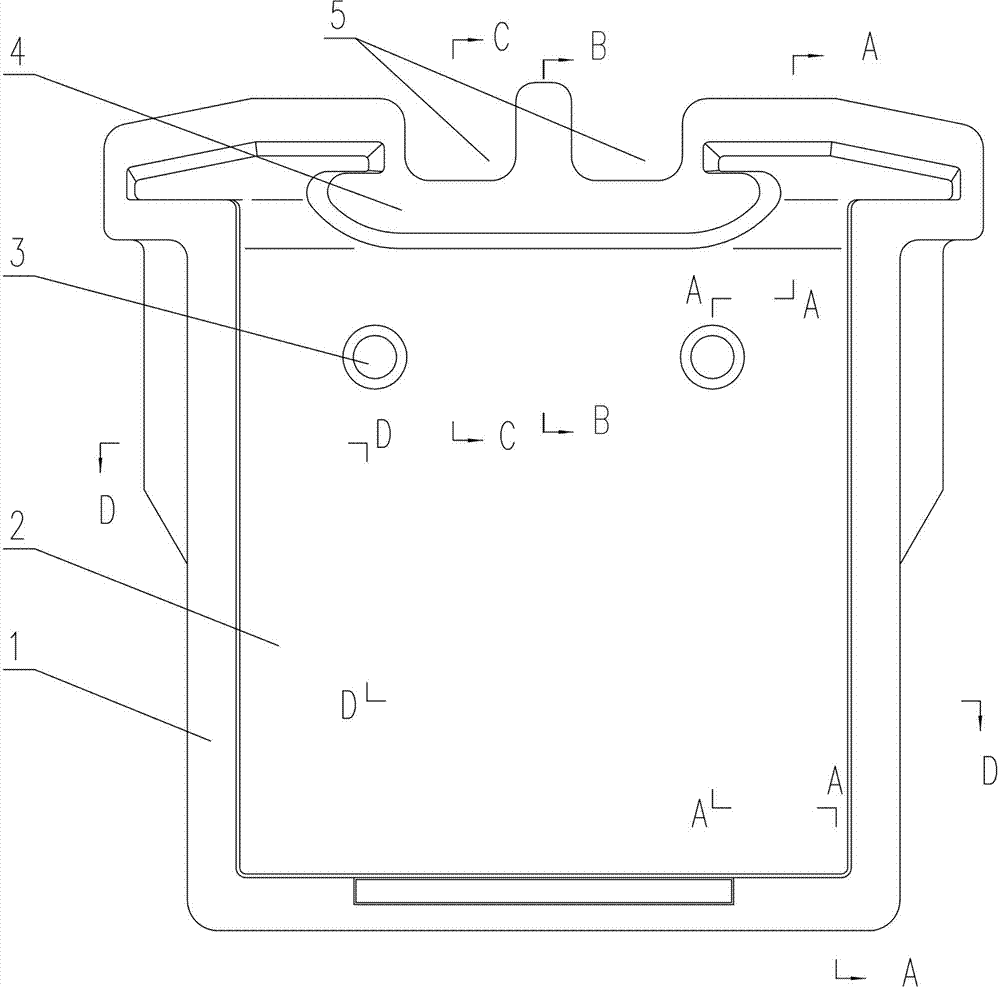
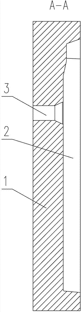
[0016] Example 1: see Figure 2-5 , a cast iron anode mold that increases the amount of copper pouring, it has a mold body 1, a copper pouring cavity 2 is opened on the mold body 1, and two release films are arranged on the mold body 1 and located on the upper part of the copper pouring cavity 2 The thimble hole 3 is characterized in that: the chemical composition weight percentage of the mold body 1 is: C: 3.6, Si: 1.6, Mn: 0.4, P<0.1, S<0.1, and the balance is Fe; the mold body There are two symmetrically arranged grooves 5 arranged in the middle section of the top of 1, forming a mountain-shaped surrounding structure 4.

[0017] Production Example 1 The production method of the cast iron anode mold with increased copper pouring amount is as follows: use 90% of the anode mold return material + 10% newborn iron, put it into the cupola for smelting, use dry mold clay sand molding, and pour the molten iron at a temperature of 1340°C , Insulated in the sand mold for 36 hours to...

example 2

[0018] Example 2: The physical structure of the cast iron anode mold of this embodiment is the same as Example 1, and its chemical composition weight percentage is: C: 3.7, Si: 1.5, Mn: 0.5, P<0.1, S<0.1, and the balance is Fe; this implementation The production method of example cast iron anode mold is basically the same as example 1, but the molten iron temperature is 1360 ℃, and the holding time in the sand mold is 38 hours.

example 3

[0019] Example 3: The physical structure of the cast iron anode mold of this embodiment is the same as Example 1, and its chemical composition weight percent is: C: 3.8, Si: 1.8, Mn: 0.6, P<0.1, S<0.1, and the balance is Fe; this implementation The production method of example cast iron anode mold is basically the same as example 1, but the molten iron temperature is 1380 ℃, and the holding time in the sand mold is 40 hours.


PUM


Abstract

The invention relates to a manufacturing mold for metallurgical industry, and in particular relates to a cast iron anode mold capable of improving copper pouring amount. The manufacturing mold is provided with a mold body, wherein a copper pouring cavity is formed on the mold body, and two demolding centre holes are formed at the upper part of the copper pouring cavity on the mold body; the cast iron anode mold is characterized in that the chemical composition of the mold body is as follows by weight percentage: 3.6-3.8% of carbon, 1.5-1.8% of silicon, 0.4-0.6% of manganese, less than 0.1% of phosphorus, less than 0.1% of sulfur and the balance of iron; two bilaterally symmetrical grooves are formed at the middle section of the top part of the mold body to form a horizontal E-shaped surrounding edge structure. The cast iron anode mold solves the problems that the existing cast iron anode mold is easy to burst and has short service life, and is mainly applied to anode copper pouring in the metallurgical industry.

Description

technical field [0001] The invention relates to a production and processing mold in the metallurgical industry, in particular to a cast iron anode mold with increased copper pouring amount and a production method thereof. Background technique [0002] The anode mold is a mold used to pour anode copper. Its working environment is very harsh. It is frequently subjected to rapid cooling and rapid heating when it is working. The temperature fluctuates greatly. During the thermal cycle, due to the obstruction of shrinkage and expansion, it produces internal stress, especially in the uneven thickness of the surrounding edge. For example, the top of the existing anode mold is flat, thick in the middle, and thin on both sides ( See figure 1 ), where the internal stress is large, which leads to cracks on the working surface or network cracks on the surface, which are connected to each other and grow up, eventually causing the anode mold to burst and be scrapped during production and...

Claims


Application Information

Patent Timeline
Patent Type & Authority Patents(China)
IPC IPC(8): B22C9/06B22D25/00C22C37/10
Inventor 杨昌凯冯汉华施小峰胡水洋张宏屏朱宏学张征魏立顺熊友波徐学军胡广生王成国秦少兵
Owner 大冶有色机电设备修造有限公司
Why Eureka
Try Eureka