Cooling water tank allowing amount of returning water to be controlled

A cooling water tank and water return technology, applied in the field of control, can solve the problems of limited experimental conditions, noisy environment, high temperature, etc., to achieve the effect of ensuring temperature control efficiency and accuracy, reducing compressors, and saving space

Inactive Publication Date: 2014-03-19
SHANDONG UNIV
View PDF5 Cites 4 Cited by
  • Summary
  • Abstract
  • Description
  • Claims
  • Application Information

AI Technical Summary

Problems solved by technology

In this experiment, due to the complex composition and high temperature of the flue gas at the tail of the boiler, it is difficult to build a simulation test bench in the laboratory, so the experiment is mainly completed in the actual operating environment of the power plant, and the experimental conditions are subject to many restrictions
For example, the layout of power plants is generally very compact, and the operating space is small. Conventional cooling water tanks with compressors are not suitable for this kind of workplace. On the other hand, the experimental conditions of power plants are simple and the environment is noisy. Experimenters hope to use as simple a controller as possible. completed experiment

Method used


Image

  • Cooling water tank allowing amount of returning water to be controlled
  • Cooling water tank allowing amount of returning water to be controlled
  • Cooling water tank allowing amount of returning water to be controlled

Examples


Embodiment 1

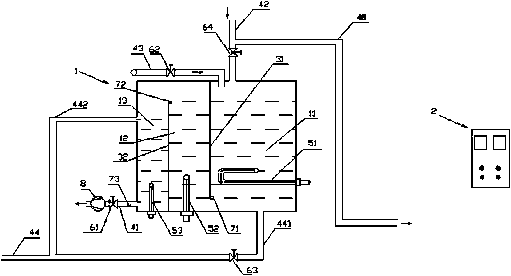
[0024] A three-stage temperature-controlled cooling water tank, including a box body 1 containing cooling water, a first partition 31 and a second partition 32 are vertically arranged in the box body 1 to separate the box body into a first box body 11 and a second box body 11. The box 12 and the third box 13, the first heating device 51 is installed in the first box 11, the discharge pipe 441 is installed at the bottom, the return pipe 42 and the water supply pipe 43 are installed at the top, and the return pipe is provided with additional drainage pipe 45 and the fourth regulating valve 64, the second heating device 52 is installed in the second box body 12, the third heating device 53 is installed in the third box body 13, and the upper part of the side wall of the third box body 13 is installed with an overflow Pipe 442, the water supply pipe 41 is installed on the lower part, the discharge pipe 441 and the overflow pipe 442 are connected with the drain pipe 44, the first bo...


PUM


Abstract

The invention relates to a cooling water tank allowing the amount of returning water to be controlled. The cooling water tank comprises a tank body holding cooling water; a first partition board and a second partition board are vertically arranged in the tank body and divide the tank body into a first tank body, a second tank body and a third tank body; a first heating device is mounted in the first tank body, a flow discharge pipe is mounted at the bottom, a water return pipe and a water replenishing pipe are mounted at the top, and a water drainage pipe and a fourth regulating valve are additionally arranged on the water return pipe; a second heating device is mounted in the second tank body; a third heating device is mounted in the third tank body, an overflow pipe is mounted at the upper part of the side wall of the third tank body, and a water supplying pipeline is mounted at the lower part; the flow discharge pipe and the overflow pipe are both connected with the water drainage pipe; the bottoms of the first tank body and the second tank body are communicated, and the tops of the second tank body and the third tank body are communicated. Compared with a traditional cooling water tank, the cooling water tank provided by the invention has the advantages that a compressor is canceled, and the space is saved; besides, the opening degree of the fourth regulating valve can be reduced, so that the flow rate of the cooling water which is subjected to heat exchange, is relatively high in temperature and returns to the tank body through the water return pipe can be controlled.

Description

technical field [0001] The invention relates to the field of control, in particular to a cooling water tank with controllable return water used in flue gas heat exchange experiments at the tail of a power plant. Background technique [0002] The cooling water tank is a commonly used instrument and equipment in the industrial and scientific research fields. In some occasions that require precise control of the cooling process parameters, such as laser cavity cooling or some scientific experiments, it is often necessary to feed cooling water with a constant temperature into the cooling pipe. . [0003] Commonly used cooling water tanks generally have two characteristics: 1. The cooling water is generally recycled, and the cooling water needs to be cooled. The cooling method is often to use a cooling device, such as compressor cooling or heat exchanger cooling. However, these cooling devices Generally, the volume is relatively large, and the use of additional cooling devices m...

Claims


Application Information

Patent Timeline
Patent Type & Authority Applications(China)
IPC IPC(8): F24H1/20F24H9/20
Inventor 马磊孙奉仲高明赵元宾
Owner SHANDONG UNIV
Why Eureka
Try Eureka