Matrix load device

A load device and matrix technology, applied in the field of electrical testing equipment, can solve the problems of time-consuming and laborious, unretrieved patents, welding quality, and temperature and humidity factors are greatly affected, and achieve accurate test data, simple and practical device, and reliability. high effect

Inactive Publication Date: 2014-03-19
天津市鑫鼎源科技发展有限公司
View PDF7 Cites 9 Cited by
  • Summary
  • Abstract
  • Description
  • Claims
  • Application Information

AI Technical Summary

Problems solved by technology

[0003] During the production process of the electric vehicle charger test platform, relevant experiments need to be carried out through the load. Since the value of the resistive load must be continuously changed in the electric vehicle charger test, and because no suitable test device can be found, manual welding was used in the past. The combination of series and parallel resistors is not only time-consuming and labor-intensive, but also the stability of the load resistor is greatly affected by the connection, welding quality, temperature and humidity factors, which directly affects the objectivity and accuracy of the test index. Among the similar products that can be found, the adjustable range series indicators cannot meet the test requirements specified in the relevant standards.
[0004] However, no relevant products have appeared in China, and no relevant patents have been retrieved from the website of the State Intellectual Property Office.

Method used


Image

  • Matrix load device
  • Matrix load device
  • Matrix load device

Examples


Embodiment

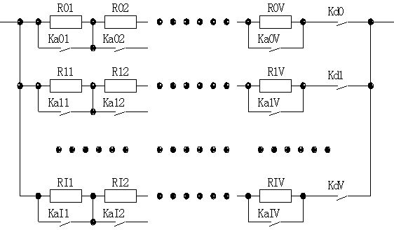
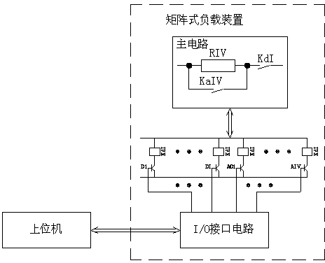
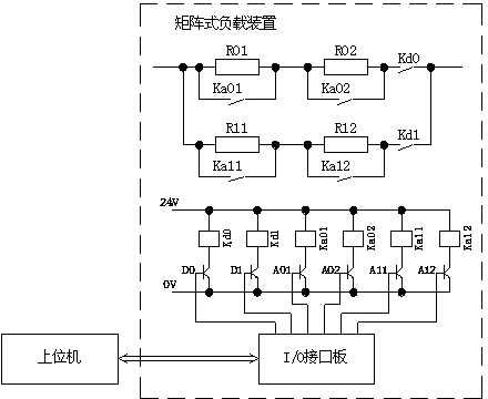
[0019] Example: such as Figure 1 to Figure 3 As shown, the matrix load device is composed of the connection of the main circuit and the control circuit;

[0020] The main circuit is composed of several branches connected in parallel; several high-precision impedances R are connected in series on each branch, and a row switch Ka is connected to both ends of each high-precision impedance R; a column switch Kd is connected in series at the end of each branch;

[0021] The high-precision impedance matrix RIV composed of high-precision impedance R, the row switch Ka, and the column switch Kd form the main circuit;

[0022] The control circuit is composed of an I / O interface circuit and a switch drive circuit; the switch drive circuit is composed of a transistor, a capacitor element or a relay;

[0023] The I / O interface circuit is composed of single-chip microcomputer or DSP (depending on the number of array combinations of the specific product to determine the model)...

Embodiment approach

[0037] Best practice includes: mounting the entire impedance array in a fan forced air cabinet;

[0038] The selection switch K and the control circuit are installed in a place where the heat of the array impedance is not affected (small);


PUM


Abstract

The invention relates to a matrix load device. The matrix load device is formed by a main circuit and a control circuit through connection; the main circuit is formed by a plurality of branches through parallel connection; every branch is formed by a high precision impedance matrix RIV comprising a high precision impedance R, line switches Ka and column switches Kd; the control circuit is formed by an I / O (Input / Output) interface circuit and a switch driving circuit such as a relay driving circuit; the I / O interface circuit is connected with an upper computer through a communication interface and receivers an instruction of the upper computer; every line switch Ka such as a contact of a relay is in parallel connection with two ends of the high precision impedance R; every column switch Kd is in series connection with the tail end of the corresponding branch; the interface circuit is controlled by the upper computer and the switch driving circuit is controlled by the interface circuit to determine the state of every switch. The matrix load device can be applied to related product detection tests of professional test stations and can be also applied to related product factory tests of production enterprises, the matrix load device is simple and practical, test data are accurate and free of deviation, the performance is stable, the reliability is high, and the practical and popularization value can be achieved.

Description

technical field [0001] The invention relates to electric appliance test equipment, in particular to a matrix type load device, which is applied to the test of electric vehicle chargers. Background technique [0002] New energy is an important strategic support point for the country's sustainable development. In order to stabilize this support point, various new energy products continue to emerge, such as electric vehicles, photovoltaic power generation, and wind power generation. Before entering the market, these new energy products have to go through the internal test of the enterprise, the type test of the national certification agency, and the license test of various industries. Any type of test requires corresponding test equipment, especially certification and licensing tests require standard test equipment. [0003] During the production process of the electric vehicle charger test platform, relevant experiments need to be carried out through the load. Since...

Claims


Application Information

Patent Timeline
Patent Type & Authority Applications(China)
IPC IPC(8): G01R1/20G01R1/28G01R31/40
Inventor 滕文车延博肖金林
Owner 天津市鑫鼎源科技发展有限公司
Why Eureka
Try Eureka