Probe calibration device

A technology for calibrating devices and calibrating brackets, which is applied to measuring devices, instruments, measuring electrical variables, etc., can solve problems such as the need to improve test accuracy, low work efficiency, and increased workload, so as to improve test accuracy and work efficiency, and has a simple structure. , the effect of improving work efficiency

Inactive Publication Date: 2014-03-19
BEIJING INST OF RADIO METROLOGY & MEASUREMENT
View PDF8 Cites 13 Cited by
  • Summary
  • Abstract
  • Description
  • Claims
  • Application Information

AI Technical Summary

Problems solved by technology

When the current laboratory test devices perform multi-position point tests in different planes of space, most of them are very simple test rods, which are tested by continuously manually moving the position of the test frame and the position of the probe on the test frame. Moving the test stand introduces movement errors and is also very inefficient
When testing in the spatial plane area and the spatial three-dimensional area, the previous test calibration frame still needs to be moved to a certain extent to complete the test of all position points, and the moved calibration frame needs to be re-referenced. A certain adjustment error also increases the workload, and it still needs to be improved in terms of test accuracy and work efficiency.

Method used


Image

  • Probe calibration device
  • Probe calibration device
  • Probe calibration device

Examples


Embodiment 1

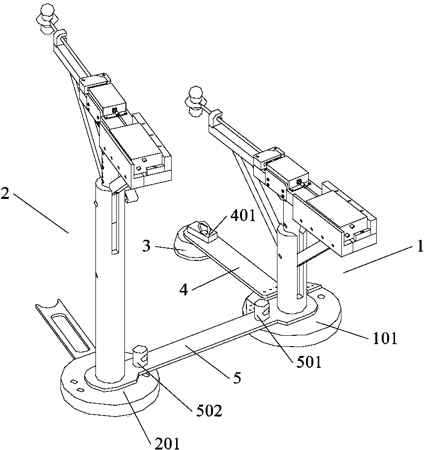
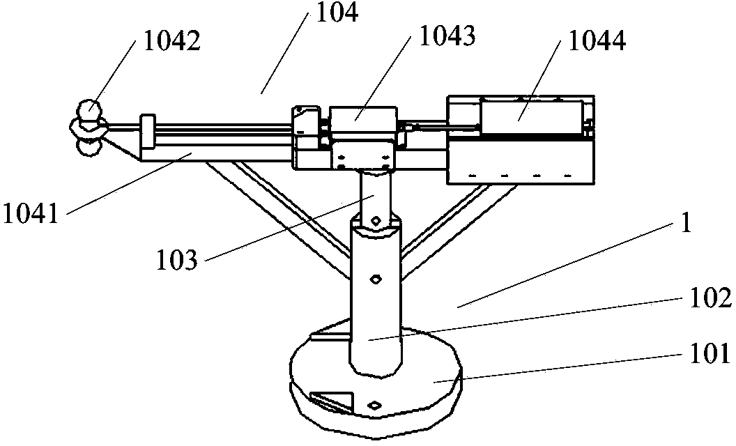
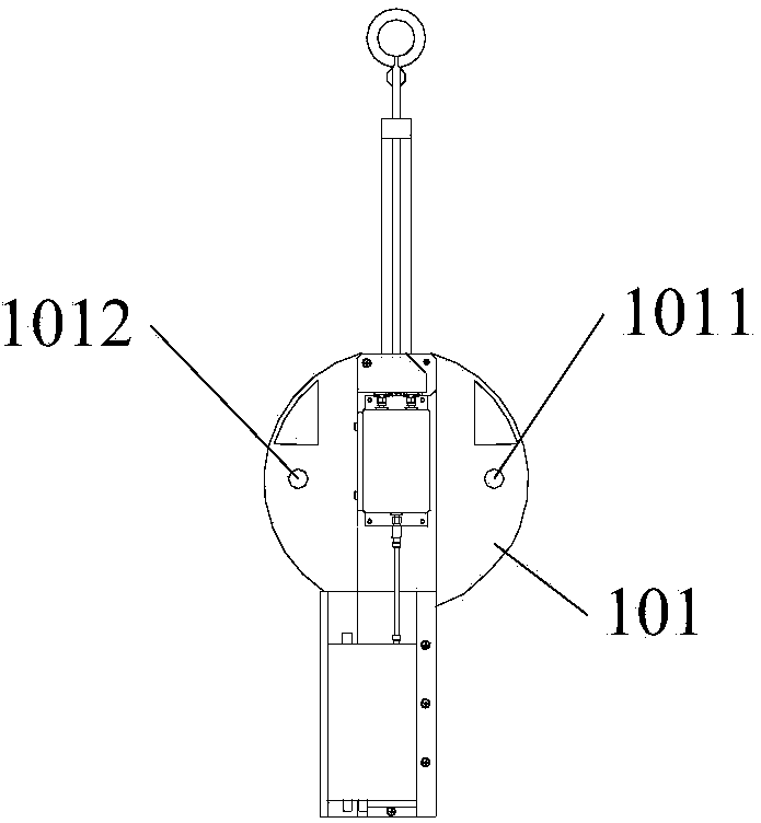
[0048] Such as Figure 9 , 10 It is a schematic diagram of the present invention when testing the planar OPMN. The plane OPMN is a square with a side length of 1 meter, the distance between the axis of the first supporting outer column 102 and the axis of the second supporting outer column 202 is 60 cm, and the distance between the axis of the fourth hole 1011 and the first measuring crossbar 1041 The included angle is 89 degrees, the included angle between the fourth hole 1011 and the fifth hole 1012 is 178 degrees, the included angle between the sixth hole 2011 and the seventh hole 2012 is 26 degrees, the seventh hole 2012 and the eighth hole The included angle between the holes 2013 is 156 degrees, and the included angle between the eighth hole 2013 and the ninth hole 2014 is 26 degrees.

[0049] When the plane test positioning starts, first use the reference hole on the positioning reference plate 3 to be orthogonal to the center line of the test area ground for referenc...

Embodiment 2

[0053] The difference between this embodiment and Embodiment 1 is: when the plane OPMN is a square with a side length of 1.5 meters, adjust the height of the first calibration bracket 1 to 0.75 meters, and adjust the height of the second calibration bracket 2 to 1.5 meters. The distance between the axis of the first supporting outer column 102 and the axis of the second supporting outer column 202 is 90 cm, the angle between the fourth hole 1011 and the axis of the first measuring cross bar 1041 is 88 degrees, the fourth hole 1011 The included angle with the fifth hole 1012 is 176 degrees, the included angle between the sixth hole 2011 and the seventh hole 2012 is 40 degrees, and the included angle between the seventh hole 2012 and the eighth hole 2013 is 144 degrees, The included angle between the eighth hole 2013 and the ninth hole 2014 is 40 degrees.

Embodiment 3

[0055] In the field uniformity calibration of transient electromagnetic fields, in addition to the RS105 test item in the US military standard 461F, there are some other test requirements for the uniformity of transient electromagnetic fields. The required test area is the 8 vertices of the cube and the midpoint of the body. Figure 11 to Figure 14 It is a schematic diagram when the present invention tests the cube ABCDEFGH. The side length of the cube ABCDEFGH is 1 meter, the height of the first calibration support 1 is adjusted to 0.5 meters, and the height of the second calibration support 2 is 1 meter. The distance between the axis of the first supporting outer column 102 and the axis of the second supporting outer column 202 is 60 cm, the angle between the fourth hole 1011 and the axis of the first measuring crossbar 1041 is 89 degrees, the fourth hole 1011 The included angle with the fifth hole 1012 is 178 degrees, the included angle between the sixth hole 2011 and the ...


PUM


Abstract

The invention discloses a probe calibration device. The probe calibration device comprises a positioning datum disc, a first calibration support and a second calibration support; wherein the first calibration support comprises a first supporting base plate, a first supporting column with one end arranged on the first supporting base plate, and a first measuring assembly arranged on the other end of the first supporting column; the second calibration support comprises a second supporting base plate, a second supporting column with one end arranged on the second supporting base plate, and a second measuring assembly arranged on the other end of the second supporting column; the positioning datum disc is connected with the first calibration support through a first connecting plate, one end of the first connecting plate is hinged to the positioning datum disc, and the other end of the first connecting plate is fixedly connected with the first supporting base plate; the first calibration support is connected with the second calibration support through a second connecting plate, one end of the second connecting plate is hinged to the first connecting base plate, and the other end of the second connecting plate is hinged to the second supporting base plate. The probe calibration device can adjust the position of a probe through simple rotation, thereby improving the accuracy of testing and work efficiency.

Description

technical field [0001] The invention relates to a probe calibration support, in particular to a probe calibration support for multi-test surface and multi-test position points by using three rotation axes. Background technique [0002] With the development of science and technology, a large number of electronic equipment is used in military equipment and civilian facilities. Once the electromagnetic pulse energy invades, the electronic components in the equipment can be invalidated or permanently damaged, causing a large-scale command, control, and communication system to be paralyzed. Electromagnetic pulse is a short-lived and transient phenomenon of strong electromagnetic radiation. Electromagnetic pulses are naturally generated or artificially produced. The most common naturally occurring electromagnetic pulses are lightning electromagnetic pulses and electrostatic discharge electromagnetic pulses. Man-made electromagnetic pulses are further divided into nuclear explosion...

Claims


Application Information

Patent Timeline
Patent Type & Authority Applications(China)
IPC IPC(8): G01R35/00G01R29/08
Inventor 黄建领康宁姚利军沈涛
Owner BEIJING INST OF RADIO METROLOGY & MEASUREMENT
Why Eureka
Try Eureka