Multifunctional electric mini tiller

A micro-tiller and multi-functional technology, applied in the field of agricultural machinery and tools, can solve the problems of unfavorable land moisture conservation, water conservation, large energy consumption and waste, and high use cost, and achieve the goal of increasing agricultural production and income, saving production costs, and saving labor costs. Effect

Inactive Publication Date: 2014-03-26
尹全权
View PDF7 Cites 1 Cited by
  • Summary
  • Abstract
  • Description
  • Claims
  • Application Information

AI Technical Summary

Problems solved by technology

[0002] Due to the unreasonable design of the pull teeth or rotary tiller teeth of the traditional micro tillage machine, the working resistance is relatively large, and the work consumed is relatively large. In addition, the mass of the engine itself is large, so it is necessary to overcome its own walking resistance during operation. At the same time, due to the useless work The proportion is far greater than the proportion of useful work, and the consumption and waste of energy are particularly large. The power generally uses a 3-5KW fuel engine to meet its power consumption, and because its power uses non-renewable disposable energy, it causes problems with The unfavorable situation of competing for energy in other fields, and the large-scale use of this high-emission, high-pollution, high-carbon energy is also not conducive to the long-term development plan of low-carbon economy and long-term sustainable development. At the same time, the manufacturing cost of this tiller Higher, higher price, higher fuel costs, higher use costs, which increase agricultural costs and reduce agricultural output benefits. In addition, the tires used in this kind of tiller have a larger diameter, and the center of gravity of the tiller is higher. The weight generally reaches more than 70 kg, and its balance is difficult to grasp, which consumes a lot of physical strength for the operator and is difficult to operate. In addition, this kind of tiller has no rollers, so it cannot crush the soil in time, and it is easy to make the soil Block air drying is not conducive to soil moisture and water conservation, and is not conducive to saving precious water resources

Method used


Image

  • Multifunctional electric mini tiller
  • Multifunctional electric mini tiller
  • Multifunctional electric mini tiller

Examples


Embodiment Construction

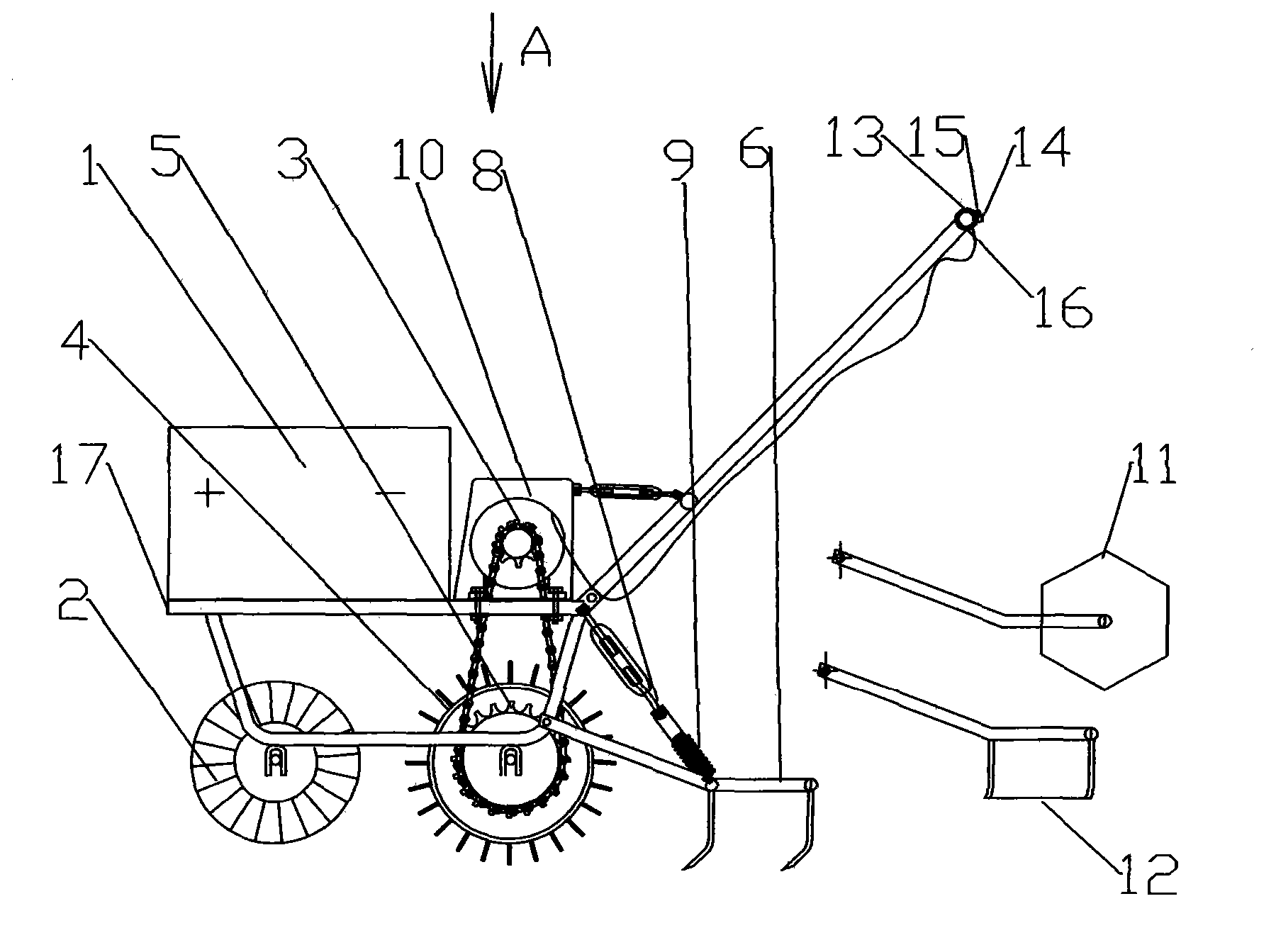
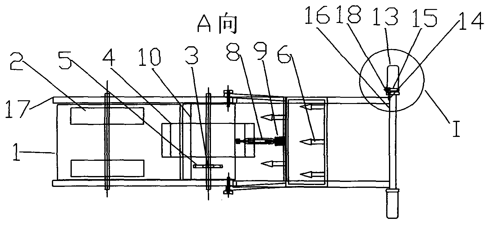
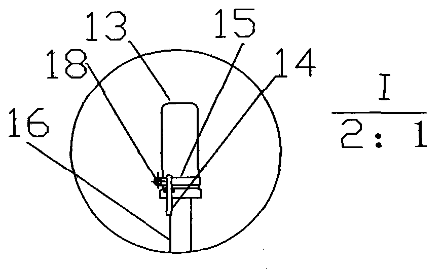
[0017] exist figure 1 , figure 2 , image 3 Among them, battery 1, motor 10, push handle 16, controller turn handle 13 are set on frame 17 top, plow share 6 is set on the right side of frame 17 bottoms, or pressure roller 11, or weeding knife 12; The 17 bottom is provided with non-operation traveling wheel 2 and operation driving wheel 4 at the same time, and operation driving wheel 4 is fixed with large sprocket 5, and large sprocket 5 is driven by chain 3 and motor 10; Turnbuckle screw 8 and pressure spring 9; Controller static limit pile 14 is set on push handle 16, and controller dynamic limit pile 15 is fixedly set by screw 18 on controller turning handle 13.

[0018] The non-operation walking wheel 2, the operation driving wheel 4, and the plowshare 6 are arranged in the following order: from left to right, in order: non-operation walking wheel 2----operation driving wheel 4----plowshare 6, left during operation March.

[0019] Controller dynamic spacer pile 15 is a...


PUM


Abstract

The invention relates to a novel agricultural implement, in particular to a multifunctional electric mini tiller. A battery, a motor, a push handle and controller rotating handles are arranged on the upper portion of a rack. The multifunctional electric mini tiller is characterized in that plough shares, press rolls or hoes are arranged on the right of the lower portion of the rack; non-operation travelling wheels and an operation driving wheel are arranged on the lower portion of the rack, a large chain wheel is fixed on the operation driving wheel, and the large chain wheel 5 is in transmission with the motor through a chain; a pressure turnbuckle and a pressure spring are arranged between the plough share and the rack; static controller limiting piles are arranged on the push handle, and dynamic controller limiting piles are arranged on the controller rotating handles fixedly through screws. The multifunctional electric mini tiller has the advantages of being environmentally friendly and low carbon as clean renewable energy resources are adopted, low in power consumption, cost and center of gravity, easy to operate, capable of completing micro tilling, hoeing and rolling at one time and timely crushing clods, beneficial to water retention and preservation of soil moisture, water resource saving and labor cost saving.

Description

technical field [0001] The invention relates to an agricultural implement, in particular to a multifunctional electric tiller. Background technique [0002] Due to the unreasonable design of the pull teeth or rotary tiller teeth of the traditional micro tillage machine, the working resistance is relatively large, and the work consumed is relatively large. In addition, the mass of the engine itself is large, so it is necessary to overcome its own walking resistance during operation. At the same time, due to the useless work The proportion is far greater than the proportion of useful work, and the consumption and waste of energy are particularly large. The power generally uses a 3-5KW fuel engine to meet its power consumption, and because its power uses non-renewable disposable energy, it causes problems with The unfavorable situation of competing for energy in other fields, and the large-scale use of this high-emission, high-pollution, high-carbon energy is also not conducive...

Claims


Application Information

Patent Timeline
Patent Type & Authority Applications(China)
IPC IPC(8): A01B3/74A01B29/00
CPCY02P60/12
Inventor 尹全权
Owner 尹全权
Why Eureka
Try Eureka