Machining technology of non-fin heat exchanger

A processing technology and heat exchanger technology, applied in heat exchange equipment, metal processing, metal processing equipment, etc., can solve problems such as low strength of welds, easy stress at joints, deformation of flat tubes, etc., to improve wettability , Improve the firmness, the effect of the weld is firm

Inactive Publication Date: 2014-03-26
GUANGZHOU JINGYI AUTOMOBILE AIR CONDITIONER
View PDF9 Cites 4 Cited by
  • Summary
  • Abstract
  • Description
  • Claims
  • Application Information

AI Technical Summary

Problems solved by technology

However, since there are no fins between the flat tubes, it is impossible to support the flat tubes, and the distance between the flat tubes is very small. During the brazing process, the flat tubes will be deformed due to thermal expansion and contraction. The connection with the tube body is prone to stress, which can easily cause the flat tubes in the formed heat exchanger to be unevenly arranged, the strength of the weld is low, and the weld seam is not beautiful. This is also a finless heat exchanger. Difficult to be widely used key

Method used


Image

  • Machining technology of non-fin heat exchanger
  • Machining technology of non-fin heat exchanger
  • Machining technology of non-fin heat exchanger

Examples


no. 1 approach

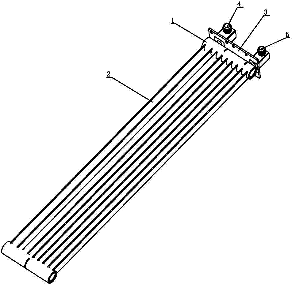
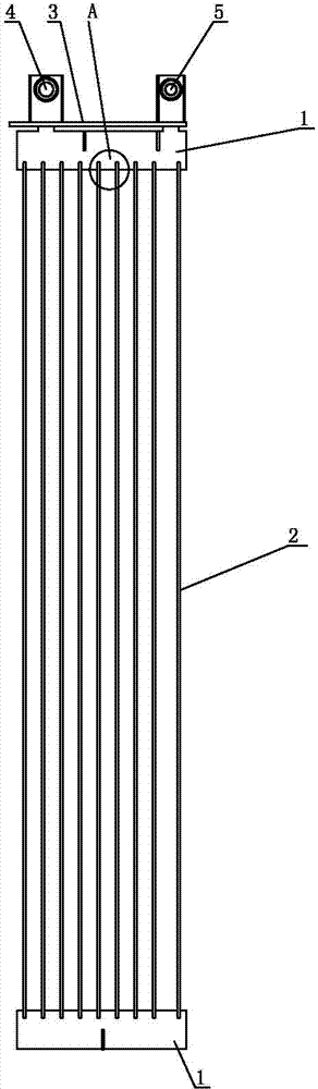
[0027] The processing technology of the finless heat exchanger includes the following steps:

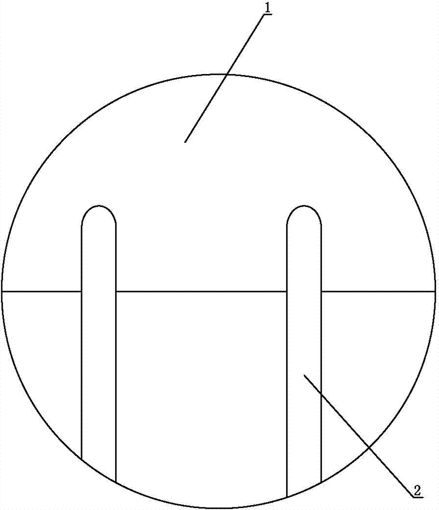
[0028] (1) On the circumference of the tube body 1, process sockets for inserting flat tubes, and the distance between adjacent sockets is 2mm;

[0029] (2) Insert the two ends of the flat tube 2 into the corresponding jacks on the tube body at both ends;

[0030] (3) Set welding positioning tool between the flat tubes; and clamp the flat tubes into the slot 7. In a group of flat tubes composed of multiple flat tubes, set different numbers of welding positions according to the length of the flat tubes. positioning tooling;

[0031] (4) Apply solder paste to the connection between the tube body and the flat tube on the tube body 1 and the flat tube 2;

[0032] (5) On both sides of the flat tube 2, strengthen the welding rods that are attached to the circumferential wall of the pipe body; On flat tube 2, adopt U-shaped reinforcing electrode, be convenient to place, locate reinforcin...

no. 2 approach

[0036] The processing technology of the finless heat exchanger includes the following steps:

[0037] (1) Process sockets for flat tube insertion on the circumference of the tube body 1, and the distance between adjacent sockets is 3mm;

[0038] (2) Insert the two ends of the flat tube 2 into the corresponding jacks on the tube body at both ends;

[0039] (3) Set welding positioning tool between the flat tubes; and clamp the flat tubes into the slot 7. In a group of flat tubes composed of multiple flat tubes, set different numbers of welding positions according to the length of the flat tubes. positioning tooling;

[0040] (4) Apply solder paste to the connection between the tube body and the flat tube on the tube body 1 and the flat tube 2;

[0041] (5) On both sides of the flat tube 2, strengthen the welding rods that are attached to the circumferential wall of the pipe body; On flat tube 2, adopt U-shaped reinforcing electrode, be convenient to place, locate reinforcing ...


PUM


Abstract

The invention discloses a machining technology of a non-fin heat exchanger. The non-fin heat exchanger comprises tube bodies and flat tubes. The machining technology of the non-fin heat exchanger comprises the following steps that (1) inserting holes are formed in the periphery of each tube body; (2) the two ends of each flat tube are inserted into the corresponding inserting holes formed in the tube bodies located at the two ends respectively; (3) a welding locating tool is arranged between every two flat tubes; each welding locating tool comprises a hollow tube, a clamping groove is formed in the tube wall of each hollow tube, and the flat tubes are clamped into the clamping grooves; (4) the portions, located on the connecting portions of the tube bodies and the flat tubes, of the tube bodies and the flat tubes are coated with soldering paste; (5) the two sides of each flat tube are respectively provided with a reinforcing welding rod attached to the circumferential walls of the corresponding tube bodies; (6) the portions, located at the connection portions of the tube bodies and the flat tubes, of the tube bodies and the flat tubes are coated with brazing flux and the mass concentration of the brazing flux is 30%-40%; (7) the tube bodies and the flat tubes are placed in a brazier together with the welding locating tools for brazing. By the adoption of the machining technology, good-quality welding of the non-fin heat exchanger is achieved.

Description

technical field [0001] The invention relates to a processing technology of a finless heat exchanger. Background technique [0002] In order to exchange heat, heat exchangers are used in various industries. A kind of heat exchanger mainly includes a tube body and a flat tube arranged between the two tube bodies, fins are arranged between the flat tubes, and an inlet tube and an outlet tube are arranged on one of the tube bodies. The heat exchange of the above structure Because of the fins, the flat tubes are evenly arranged, and stress is not easily generated during the brazing process. The strength of the weld is high and will not affect the appearance of the weld, and the fins can support the flat tubes. The role of the heat exchanger makes the strength of the heat exchanger high. In addition, the fins can greatly increase the heat exchange area, so the heat exchange efficiency is high. However, after the fins are provided, the volume of the heat exchanger is large, so it...

Claims


Application Information

Patent Timeline
Patent Type & Authority Applications(China)
IPC IPC(8): B23K1/008
CPCB23K1/008B23K1/20B23K1/203B23K2101/14B23K2103/16
Inventor 蔡静斌周玉文
Owner GUANGZHOU JINGYI AUTOMOBILE AIR CONDITIONER
Why Eureka
Try Eureka