Tyre cord layer jointing device and jointing method

A joining device and joining method technology, applied in tires, applications, household appliances, etc., can solve problems such as inability to maintain joining force, reduced productivity, and separation of joining parts.

Inactive Publication Date: 2014-03-26
SUMITOMO RUBBER IND LTD
View PDF2 Cites 10 Cited by
  • Summary
  • Abstract
  • Description
  • Claims
  • Application Information

AI Technical Summary

Problems solved by technology

[0010] That is, in the lap joint method, if the overlapping portion is less than 3 mm and the joint is performed, sufficient joint force cannot be maintained, and the joint portion may be separated during expansion.
[0015] In this case, productivity is further reduced due to the increased work of cutting both edges, and additional costs are incurred for disposing of waste rubber generated by cutting

Method used


Image

  • Tyre cord layer jointing device and jointing method
  • Tyre cord layer jointing device and jointing method
  • Tyre cord layer jointing device and jointing method

Examples


no. 1 approach

[0060] (1) Structure of the joining device for tire cord layers

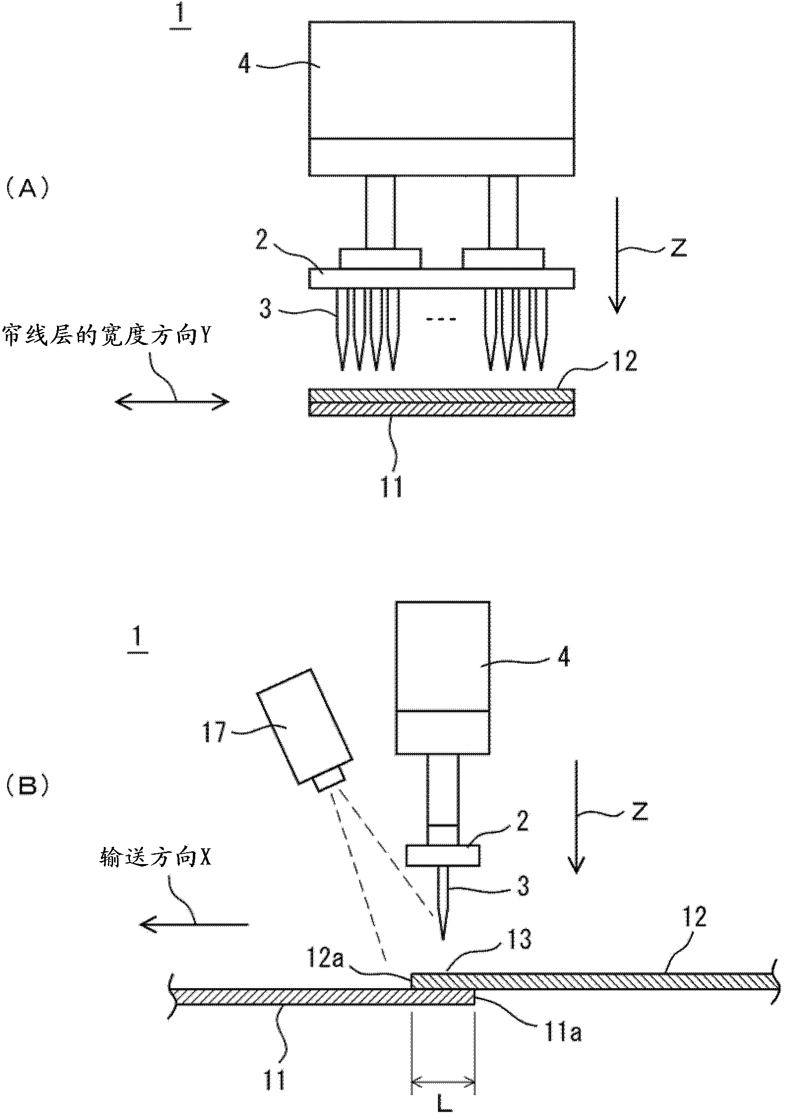
[0061] figure 1 It is a figure which shows the 1st Embodiment of the joining apparatus of the cord layer for tires concerning this invention, figure 1 (A) is a brief side view, figure 1 (B) is a brief front view.

[0062] The joining apparatus 1 is an apparatus for manufacturing a long carcass cord or the like by repeatedly overlapping and joining edge portions of two cord layers.

[0063] like figure 1 As shown, the joining device 1 is equipped with: an elevating member 2 provided with a plurality of acicular protrusions 3; an actuator 4 as a driving unit of the elevating member; And the belt conveyor (not shown) which forms the overlapping part 13. in addition, figure 1 Also shown in FIG. 2 is a position sensor 17 that detects the position of the cord layers 11 , 12 conveyed in the conveying direction X by means of a belt conveyor.

[0064] The elevating member 2 is arranged above the overlapping portio...

no. 2 approach

[0084] (1) Structure of the joining device for tire cord layers

[0085] Figure 5 It is an enlarged front view of main parts showing a second embodiment of the tire cord ply joining device.

[0086] In the joining device 21 of the second embodiment, the shape of the tip of the needle-like protrusion 23 provided on the elevating member 2 is a flat surface, and a laser scanning sensor 28 for detecting minute unevenness on the surface of the upper cord layer 12 is provided, Other than that, the rest is the same as the joining device 1 of the first embodiment, and only the parts different from the first embodiment will be described below.

[0087] like Figure 5 As shown, the tip portion 23a of the acicular protrusion 23 in this embodiment is formed as a flat surface with a diameter of 0.3 mm to 0.5 mm.

[0088] The laser scanning sensor 28 is installed near the lifting member, and detects the position of the cords 15 constituting the cord layer 12 by detecting minute unevenne...

Embodiment

[0099] Next, the state of joining was evaluated by joining edge portions of two cord layers having different overlapping amounts to perform tensile evaluation.

[0100] 1. Test body

[0101] Use two cord layers with a size of 525mm×1450mm×0.95mm (thickness) (the number of cords is 1450), and as shown in Table 1, use less than 3mm (1 to 2 cords), 3mm or more (3 or more cords) overlapping amount was joined to prepare a test body. In addition, as a test body of less than 3 mm, a test body obtained by cutting and joining two edges was prepared.

[0102] 2. Joining method

[0103] As the joining method, the joining method based on the first embodiment (Example), the joining method based on the conventional lap joint method (Comparative Example 1), and the joining method based on the zipper joint method (Comparative Example 2) were used.

[0104] 3. Evaluation method

[0105] Assuming that expansion occurs, each test body is stretched using a tensile shear machine (shear force: ...


PUM

PropertyMeasurementUnit
diameteraaaaaaaaaa

Abstract

The invention provides a tyre cord layer jointing device and jointing method. Accordingly, tyres with excellent high-speed uniformity can be manufactured at a high production rate without needing reserving a relatively large amount of rubber among cords or pre-cutting the two edges of each cord layer in a mode that even a relatively small overlapped part can still reliably joint the cord layers with a stable strength. The tyre cord layer jointing device comprises an elevating part and an elevating unit. Needle-shaped projections are distributed on the elevating part at specified intervals along the width direction of the two cord layers. Each of the cord layers is formed by using unvulcanized rubber to cover a cord arrangement body which is formed by parallelly arranging the cords. The elevating unit enables the needle-shaped projections to spur the overlapped part until the front end parts of the needle-shaped projections penetrate through the overlapped part. Moreover, the elevating unit enables the elevating part to lower down to make the unvulcanized rubber of one cord layer invade into the other cord layer and then enables the elevating part to rise up to pull the needle-shaped projections out of the overlapped part after the spurring.

Description

technical field [0001] The present invention relates to a joining device and joining method of cord layers for tires. Background technique [0002] In the biasing process of the cord layers in the tire manufacturing process, after the cord layers are cut to a predetermined width at a predetermined angle, the edge portions (edges) of the two cord layers obtained after cutting are joined to each other These two cord layers are elongated (for example, Patent Document 1 and Patent Document 2), wherein the cord layers are formed by covering a cord array body in which cords are arranged in parallel with unvulcanized rubber. [0003] In addition, as such joining methods, conventionally, lap joints, zip joints, and butt joints shown below have been employed. [0004] The lap splicing method is a method in which the overlapped portion in which the edge portions of the two cord layers overlap each other up and down is pressed simultaneously from the vertical direction as it is to joi...

Claims


Application Information

Patent Timeline
Patent Type & Authority Applications(China)
IPC IPC(8): B29C65/72B29C65/54B29L30/00
Inventor 冈田知之
Owner SUMITOMO RUBBER IND LTD
Why Eureka
Try Eureka