Method for recovering hydrogen and ammonia in synthetic ammonia exhausted gas

A technology for synthesizing ammonia degassing and hydrogen, applied in the direction of ammonia preparation/separation, hydrogen separation, hydrogen separation using solid contact, etc., can solve the problems of irreversible and damaged downstream separation membranes, and reduce energy consumption and operating costs , the effect of reducing land occupation

Active Publication Date: 2014-03-26
DALIAN EUROFILM IND
View PDF5 Cites 2 Cited by
  • Summary
  • Abstract
  • Description
  • Claims
  • Application Information

AI Technical Summary

Problems solved by technology

The above method has very strict requirements on the operation of the ammonia absorption tower. The concentration of ammonia in the gas phase must not exceed the standard, and the occurrence of mist entrainment and liquid flooding must be absolutely avoided, otherwise it will cause irreversible damage to the downstream separation membrane.

Method used


Image

  • Method for recovering hydrogen and ammonia in synthetic ammonia exhausted gas
  • Method for recovering hydrogen and ammonia in synthetic ammonia exhausted gas

Examples


Embodiment 1

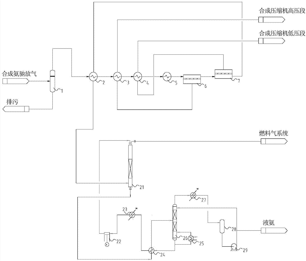
[0026] exist figure 1 In the process schematic diagram of the method example 1 for recovering hydrogen and ammonia in the synthetic ammonia purge gas shown, the synthetic ammonia purge gas discharged by the synthesis system has a discharge pressure of 13MPa, a temperature of 26°C, and a gas volume of 12000Nm3 / hr. as follows:

[0027] components

[0028] The purge gas first enters the filter 1 to remove solid particles and liquid droplets that may be entrained by the air flow, and the filtered impurities are discharged from the bottom of the filter 1. The filtered gas passes through the first-stage heat exchanger 2, exchanges heat with the trapped gas of the second-stage separation membrane, raises the temperature of the gas to 41.8°C, and then passes through the second-stage heat exchanger 3 to separate from the first stage The heat exchange of the permeated gas of the membrane raises the temperature of the gas to 47.5°C, and then passes through the third-stage heat...

Embodiment 2

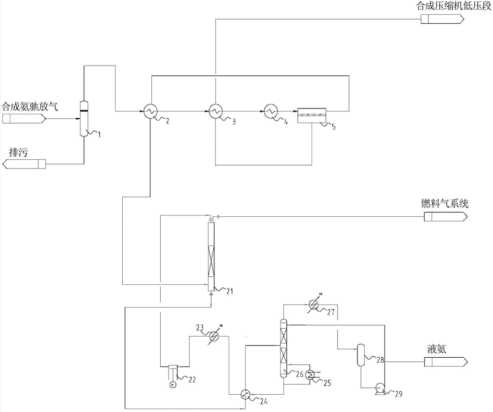
[0040] exist figure 2 In the process schematic diagram of the method example 2 of the shown recovery of hydrogen and ammonia in the synthetic ammonia purge gas, the synthetic ammonia purge gas discharged by the synthesis system has a discharge pressure of 12.3MPa, a temperature of 25°C, and a gas volume of 8000Nm3 / hr. The composition is as follows:

[0041] components

H 2

N 2

CH 4

Ar

NH 3

Content% (V / V)

63.00

21.84

8.10

3.55

3.50

[0042] The purge gas first enters the filter 1 to remove solid particles and liquid droplets that may be entrained by the air flow, and the filtered impurities are discharged from the bottom of the filter 1. The filtered gas passes through the first-stage heat exchanger 2, exchanges heat with the trapped gas separated by the membrane, raises the temperature of the gas to 37.68°C, and then passes through the second-stage heat exchanger 3, exchanges heat with the permeated gas separa...


PUM


Abstract

The method discloses a method for recovering hydrogen and ammonia in synthetic ammonia exhausted gas. The method comprises a pretreatment process, a membrane separation process and an ammonia recovering process; and an ammonia resistant membrane which can tolerate an ammonia gas phase with concentration lower than 6% (v / v) for a long time is adopted to treat the synthetic ammonia exhausted gas, hydrogen and most ammonia in the synthetic ammonia exhausted gas are recovered, and then ammonia contained in retention gas after membrane separation is recovered with methods of water washing and ammonia distillation and changed into a liquid ammonia product. According to the method for recovering hydrogen and ammonia in the synthetic ammonia exhausted gas, safe and stable operation of the membrane separation process is guaranteed essentially, and more than 85% of hydrogen and more than 75% of ammonia can be recovered; equipment investment and occupied land involved in the ammonia recovering process are reduced by 60%; and meanwhile, energy consumption of an ammonia absorption tower and an ammonia still is reduced by 70%-80%, and the operation cost is reduced by 70%-80%.

Description

technical field [0001] The invention belongs to the technical field of recovery of synthetic ammonia purge gas, and in particular relates to a method for recovering hydrogen and ammonia from synthetic ammonia purge gas. Background technique [0002] In the production process of synthetic ammonia, hydrogen and nitrogen are the raw materials of synthetic ammonia. Nitrogen is generally separated from air, and hydrogen is generally obtained through natural gas conversion or coal gasification. Hydrogen and nitrogen react under high pressure and temperature and under the action of a catalyst to produce ammonia. Restricted by the chemical balance, the reactants cannot be completely converted, and the unreacted nitrogen and hydrogen are mixed with the supplementary fresh gas through the circulating compressor and then enter the synthesis tower for the ammonia synthesis reaction. Since nitrogen and hydrogen, raw materials for ammonia synthesis, contain a certain amount of inert comp...

Claims


Application Information

Patent Timeline
Patent Type & Authority Applications(China)
IPC IPC(8): C01B3/56C01C1/12
Inventor 马艳勋李泰胧杜国栋栗广勇李恕广
Owner DALIAN EUROFILM IND
Why Eureka
Try Eureka