A Calibration Method for On-orbit Optical Distortion Parameters of a Linear Array Pushbroom Camera

A linear array push-broom, optical distortion technology, applied in the field of remote sensing satellite image processing, can solve problems such as restricting the application performance of high-resolution satellite images, large internal distortion, and inability to meet the requirements of orthophoto product production.

Active Publication Date: 2016-09-21
SPACE STAR TECH CO LTD
View PDF5 Cites 0 Cited by
  • Summary
  • Abstract
  • Description
  • Claims
  • Application Information

AI Technical Summary

Problems solved by technology

Although the geometric positioning accuracy of domestic satellites is gradually improving, compared with foreign commercial high-resolution optical remote sensing satellites such as Geoeye, WorldView, Pleiades, etc., there is still a big gap in the geometric positioning accuracy of domestic satellites, especially the internal geometric accuracy of images. It cannot meet the production requirements of orthophoto products in the fields of land resources, surveying and mapping, etc., which seriously restricts the application performance of high-resolution satellite images in my country
[0004] Affected by launch momentum, on-orbit environment and other factors, the internal geometric distortion parameters of the aerospace remote sensing optical camera have changed greatly after the orbit, and the internal parameters of the camera measured on the ground will lead to large internal distortion when used for image geometric processing. Distortion, especially the internal distortion of images far away from the main point can reach the order of 30 meters, which seriously restricts the improvement of its positioning accuracy and affects subsequent advanced applications such as image mosaic mosaic

Method used


Image

  • A Calibration Method for On-orbit Optical Distortion Parameters of a Linear Array Pushbroom Camera
  • A Calibration Method for On-orbit Optical Distortion Parameters of a Linear Array Pushbroom Camera
  • A Calibration Method for On-orbit Optical Distortion Parameters of a Linear Array Pushbroom Camera

Examples


Embodiment Construction

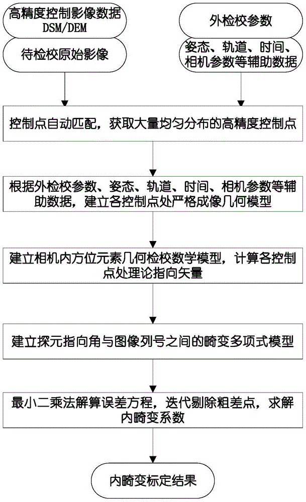
[0031] Attached below figure 1 , figure 2 Specific embodiments of the present invention are further described in detail:

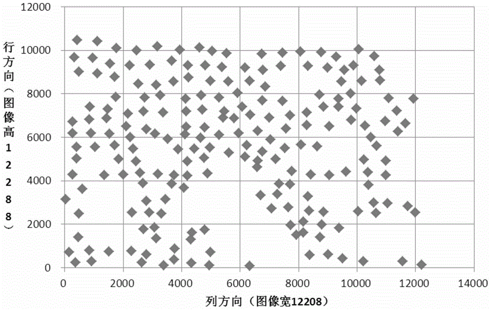
[0032] 1. In the image to be checked I 1 , high-precision control image I 2 The control point automatic matching algorithm is used to collect high-precision control point information.

[0033] (1) The original image to be corrected based on SIFT algorithm I 1 Perform feature point extraction to obtain M feature points PixI 1n (n=1,2...,M), record the SIFT feature vector of each feature point;

[0034] The SIFT feature matching algorithm is characterized as follows:

[0035] (1.1) Determine the position coordinates and scale of the feature points. Build an image Gaussian pyramid, and detect extreme values ​​in the 26 neighborhoods in the pyramid scale space. If a point (x, y) is the maximum or minimum value in the 26 neighborhoods of the pyramid scale space and the upper and lower layers , defining this point as a feature point of the image at this...


PUM


Abstract

A calibration method for on-orbit optical distortion parameters of a linear array push-broom camera, the steps of which are: (1) adopt an automatic matching algorithm based on control points to collect dense and high-precision control point information; (2) establish strict imaging at each control point Geometric model; (3) Calculate the theoretical pointing vector and actual pointing vector of each control point, and establish a mathematical model for geometric correction of the orientation elements in the camera; (4) Establish a distortion polynomial model corresponding to the theoretical pointing vector and the image column number; (5) The least squares method is used to solve the error equation, and the iterative solution is used to obtain the calibration parameters of the internal optical distortion of the camera. The invention calibrates the distortion of the internal optical system of the satellite on-orbit camera by selecting a large number of high-precision ground control points. The calibration results can be used to improve the uncontrolled positioning accuracy and the controlled positioning accuracy of the satellite image, and use the internal distortion calibration parameters to determine the internal orientation elements of the camera. After correction, the internal distortion of the image is basically eliminated.

Description

technical field [0001] The invention relates to a calibration method for on-orbit optical distortion parameters of a linear array push-broom camera, which belongs to the technical field of remote sensing satellite image processing and is used for optimizing and improving the on-orbit positioning accuracy of a linear push-broom camera mounted on a remote sensing satellite and improving the internal geometric quality of the image improvement optimization. Background technique [0002] With the continuous development of space technology, satellite remote sensing imagery has become an important data source for current geospatial information services and applications, and its wide application prospects have attracted widespread attention from all over the world. Compared with the ability to obtain high-resolution satellite data a few years ago, countries around the world have been scrambling to develop their own high-resolution earth observation systems in recent years, and the s...

Claims


Application Information

Patent Timeline
Patent Type & Authority Patents(China)
IPC IPC(8): G01C11/02G03B43/00
CPCG01C25/00
Inventor 马灵霞郝胜勇王剑邹同元丁火平马狄郭翠翠张荞纪强李宝明
Owner SPACE STAR TECH CO LTD
Why Eureka
Try Eureka