
A gas pressure type optical fiber Bragg grating temperature sensor and its application method

A temperature sensor and gas pressure technology, applied in thermometers, thermometers with physical/chemical changes, instruments, etc., can solve problems such as use restrictions, achieve adjustable temperature measurement sensitivity, and achieve the effect of measuring range

Inactive Publication Date: 2016-08-17
KUNMING UNIV OF SCI & TECH
View PDF7 Cites 0 Cited by
  • Summary
  • Abstract
  • Description
  • Claims
  • Application Information

AI Technical Summary

Problems solved by technology

Due to the laser device installed on the rotating rod, its use in petroleum, chemical and other flammable and explosive occasions is limited

Method used


Image

  • A gas pressure type optical fiber Bragg grating temperature sensor and its application method
  • A gas pressure type optical fiber Bragg grating temperature sensor and its application method
  • A gas pressure type optical fiber Bragg grating temperature sensor and its application method

Examples


Embodiment approach 1

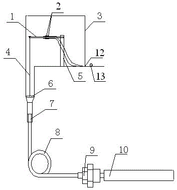
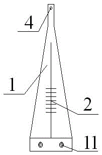
[0055] Implementation mode one: if figure 1 Shown, the structure of gas pressure type optical fiber Bragg grating temperature sensor of the present invention: comprise gas pressure temperature sensing device and optical fiber Bragg grating pressure conversion device, gas pressure temperature sensing device is connected capillary 8 and isolation tube 8 by sealed temperature change pressure sensing bag 10 Layer diaphragm 6; the main body of the optical fiber Bragg grating pressure conversion device is an equal-intensity cantilever beam 1 equipped with an optical fiber Bragg grating 2, and one end of the equal-intensity cantilever beam 1 transmits the pressure sensed by the gas pressure temperature sensing device through the interlayer diaphragm 6 ; The fiber Bragg grating 2 is connected to the external optical cable 13 to transmit the sensed signal. The equal-strength cantilever beam 1 is rigidly connected to the interlayer diaphragm 6 through the pressure transmission rod 4 , a...

Embodiment approach 2

[0069] Implementation mode two: if figure 1 Shown, the structure of gas pressure type optical fiber Bragg grating temperature sensor of the present invention: comprise gas pressure temperature sensing device and optical fiber Bragg grating pressure conversion device, gas pressure temperature sensing device is connected capillary 8 and isolation tube 8 by sealed temperature change pressure sensing bag 10 Layer diaphragm 6; the main body of the optical fiber Bragg grating pressure conversion device is an equal-intensity cantilever beam 1 equipped with an optical fiber Bragg grating 2, and one end of the equal-intensity cantilever beam 1 transmits the pressure sensed by the gas pressure temperature sensing device through the interlayer diaphragm 6 ; The fiber Bragg grating 2 is connected to the external optical cable 13 to transmit the sensed signal. The equal-strength cantilever beam 1 is rigidly connected to the interlayer diaphragm 6 through the pressure transmission rod 4 , a...


PUM

PropertyMeasurementUnit
wavelengthaaaaaaaaaa

Abstract

The invention relates to a gas pressure type optical fiber Bragg grating temperature sensor and a using method thereof, belonging to the technical field of optoelectronic measuring devices. It includes a gas pressure temperature sensing device and an optical fiber Bragg grating pressure conversion device. The gas pressure temperature sensing device is connected by a sealed temperature change pressure sensing package to a capillary and an interlayer diaphragm; the main body of the optical fiber Bragg grating pressure conversion device is installed with a fiber Bragg grating Equal-strength cantilever beam, one end of the equal-strength cantilever beam transmits the pressure sensed by the gas pressure and temperature sensing device through the interlayer diaphragm. The temperature change pressure sensing package is placed in the temperature environment to be measured, and the real-time online monitoring of the measured temperature is realized according to the established mathematical model between the measured ambient temperature T and the wavelength shift ΔλB1,2 of the fiber Bragg grating.

Description

technical field [0001] The invention relates to a gas pressure type optical fiber Bragg grating temperature sensor and a using method thereof, belonging to the technical field of optoelectronic measuring devices. Background technique [0002] Temperature is a state parameter that describes the thermal properties of a substance. With the development of science and technology and the progress of modern industrial technology, in many fields of industrial production, the requirements for temperature measurement continue to increase. Especially for temperature detection in high-risk environments such as petroleum and chemical industry, temperature sensors are required to have the characteristics of high safety, good insulation, and anti-electromagnetic interference. Traditional temperature sensors based on electrical signal transmission are difficult to meet the application needs in high-risk environments. Due to the intrinsically safe characteristics of optical fiber, it has b...

Claims


Application Information

Patent Timeline
Patent Type & Authority Patents(China)
IPC IPC(8): G01K11/32G01K11/3206
Inventor 李川陈富云赵成均王敏吉刘江赵振刚谢涛李英娜
Owner KUNMING UNIV OF SCI & TECH
Learn More