Device and method for measuring backscattering of laser gyroscope ultra-smooth reflecting mirror

A technology of backscattering and laser gyroscope, applied in the field of laser gyroscope, can solve the problems of reducing the blocking threshold of laser gyroscope, not very effective, etc., and achieve the effect of convenient operation and high measurement accuracy

Active Publication Date: 2014-03-26
FLIGHT AUTOMATIC CONTROL RES INST
View PDF6 Cites 8 Cited by
  • Summary
  • Abstract
  • Description
  • Claims
  • Application Information

AI Technical Summary

Problems solved by technology

Since the interference intensity is not only related to the backscattering intensity of each mirror, but also its phase angle, and the thermal expansion of the ring resonator will change the phase angle, the laser gyro can be reduced by measuring and controlling the backscattering of the ring resonator The latch-off threshold is not very effective

Method used


Image

  • Device and method for measuring backscattering of laser gyroscope ultra-smooth reflecting mirror
  • Device and method for measuring backscattering of laser gyroscope ultra-smooth reflecting mirror
  • Device and method for measuring backscattering of laser gyroscope ultra-smooth reflecting mirror

Examples


Embodiment Construction

[0031] The present invention will be further described below by means of specific embodiments:

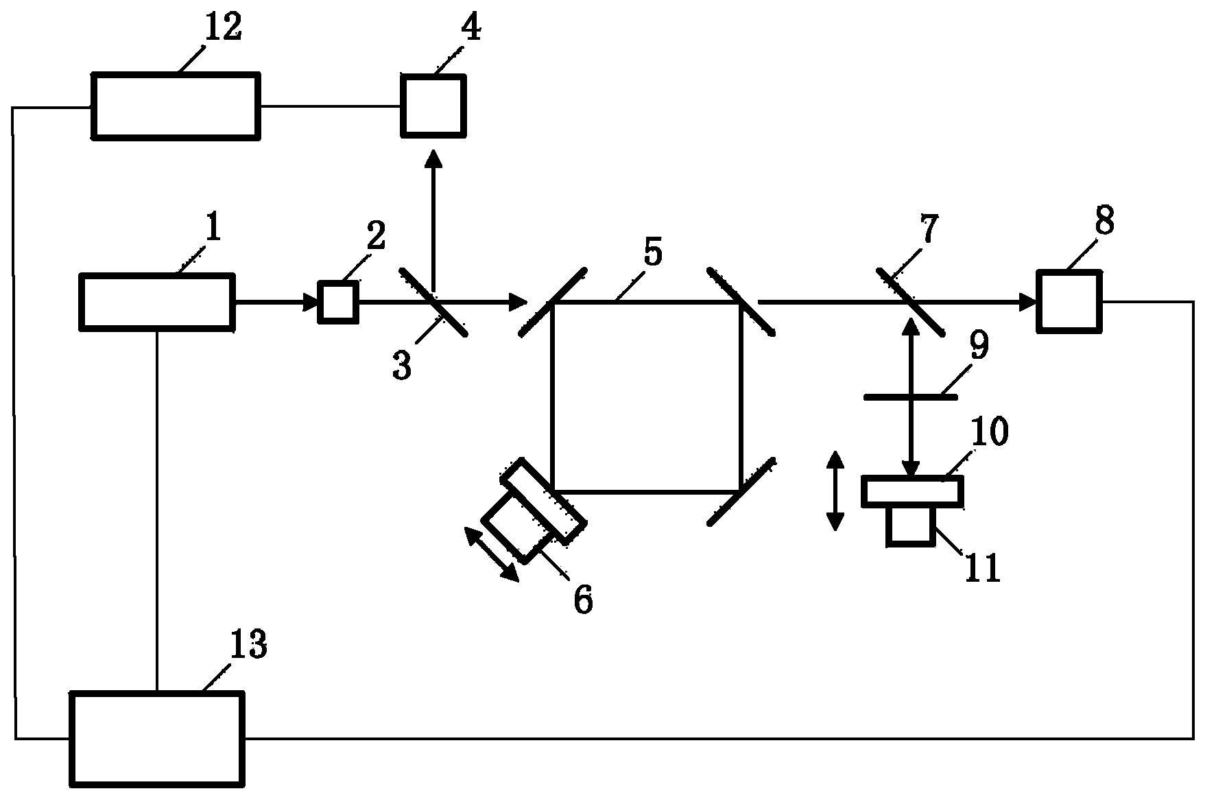
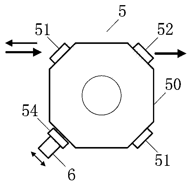
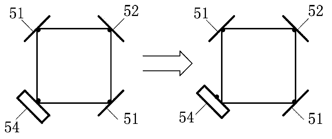
[0032] see figure 1 , which is a schematic diagram of the principle of a preferred embodiment of the laser gyro ultra-smooth mirror backscatter measurement device of the present invention. In this embodiment, the laser gyro ultra-smooth mirror backscatter measurement device includes a He-Ne laser 1, a Faraday optical isolator 2, a beam splitter A3, a photodetector A4, a ring resonator 5, and a micromanipulator A6 , beam splitter B7, photodetector B8, optical filter 9, feedback mirror 10, micromanipulator B11, lock-in amplifier 12, frequency stabilization system 13. Among them, the output beam of He-Ne laser 1 is incident into Faraday optical isolator 2, beam splitter A3, ring resonator 5, and beam splitter B7 in sequence; the outgoing light of beam splitter B7 is divided into two beams, and one beam is incident into The photodetector B8, another beam is incident on the optical fi...


PUM


Abstract

The invention belongs to the laser gyroscope technology, and relates to a device and method for measuring backscattering of a laser gyroscope ultra-smooth reflecting mirror. The device comprises an optical laser, a Faraday opto-isolator, a beam splitter A, a photoelectric intrusion-detector A, a ring-shaped resonant cavity, a micro-manipulator A, a beam splitter B, a photoelectric intrusion-detector B, an optical filter, a feedback mirror, a micro-manipulator B, a phase-locking amplifier and a frequency stabilization system. According to the invention, a part of energy of a pumping light beam is fed back to the ring-shaped resonant cavity to be in optical interference with backscattering in the cavity to improve the signal-to-noise ratio of backscattering signals of the ring-shaped resonant cavity; a reflecting mirror to be measured is enabled to move slightly along the mirror surface tangential direction to achieve accurate measurement for backscattering amplitude coefficient of the ultra-smooth reflecting mirror used by a laser gyroscope; the ultra-smooth reflecting mirror with small backscattering can be selected to be used for the adjustment of the laser gyroscope resonant cavity, so that important significance of reducing laser gyroscope locking areas and improving laser gyroscope precision is achieved.

Description

technical field [0001] The invention belongs to laser gyro technology, and relates to a laser gyro ultra-smooth mirror backscattering measurement device and method. Background technique [0002] As the angle sensor of choice for high-precision inertial navigation systems, laser gyroscopes have been widely used in aircraft, ships, submarines, missiles and military vehicles. The backscattering on the mirror surface of the laser gyroscope will cause the latch-up effect, increase the random walk, and reduce the accuracy of the laser gyroscope. In order to reduce the backscattering and the lock-up threshold caused by it, and improve the accuracy of the gyroscope, manufacturers generally use mirrors with ultra-smooth surfaces to manufacture laser gyroscopes, and their surface roughness is usually less than 1nm. [0003] When evaluating the quality of ultra-smooth mirrors used in laser gyroscopes, the total integral scattering method is generally used, that is, the surface roughne...

Claims


Application Information

Patent Timeline
Patent Type & Authority Applications(China)
IPC IPC(8): G01M11/02
Inventor 王珂王京献韩宗虎徐宏财张自国
Owner FLIGHT AUTOMATIC CONTROL RES INST
Why Eureka
Try Eureka