
Rotor eccentricity preventing structure

A technology of rotor eccentricity and rotor, which is applied in the field of rotor eccentricity prevention structure, and can solve problems such as deformation

Inactive Publication Date: 2014-03-26
HYUNDAI MOBIS CO LTD
View PDF7 Cites 7 Cited by
  • Summary
  • Abstract
  • Description
  • Claims
  • Application Information

AI Technical Summary

Problems solved by technology

[0010] However, for the rotating shaft connection structure of the above structure, if it is a Radial Flux motor that forms a magnetic field in the radiation direction, even if the rotating shaft thermally expands, it will have little effect on the gap between the rotor and the stator core, and the magnetic field will rotate in the direction of rotation. In the Axial Flux motor formed in the axial direction of the shaft, the gap between the rotor and the stator is deformed due to the thermal expansion of the rotating shaft

Method used


Image

  • Rotor eccentricity preventing structure
  • Rotor eccentricity preventing structure
  • Rotor eccentricity preventing structure

Examples


Embodiment Construction

[0035] The rotor eccentricity prevention structure of the preferred embodiment of the present invention will be described in detail below in conjunction with the accompanying drawings.

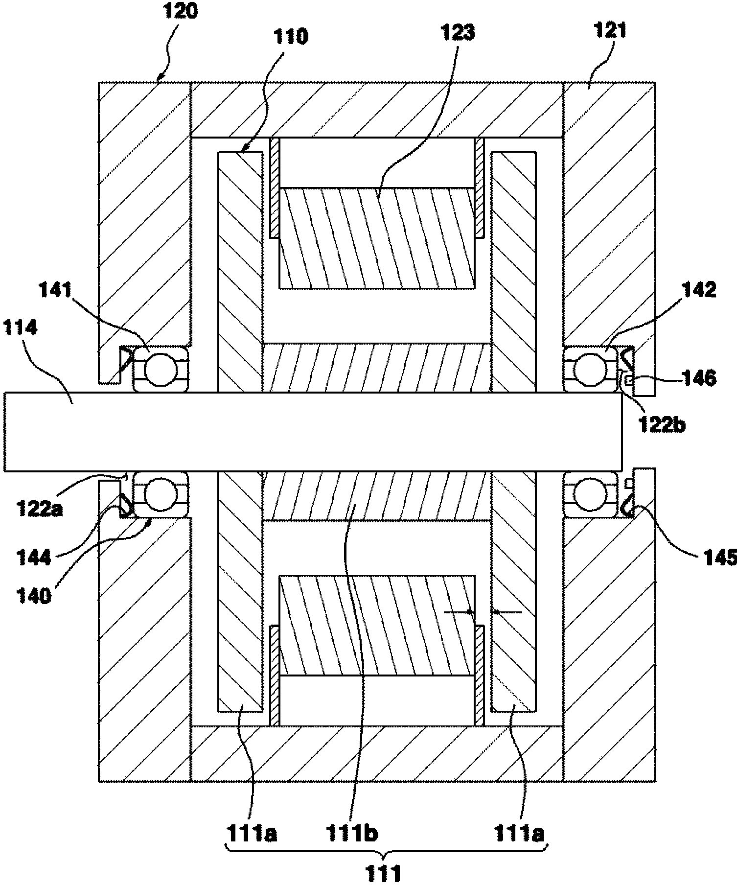
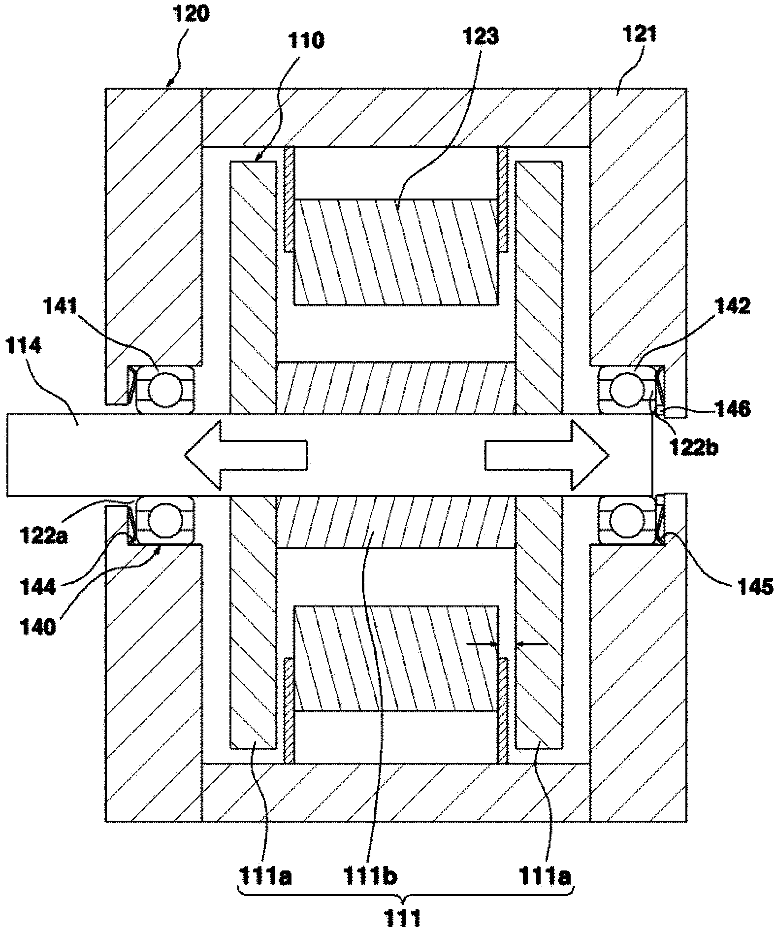
[0036] figure 1 As shown, the rotor eccentricity prevention structure 140 of the preferred embodiment of the present invention can be assembled on the motor 100 .

[0037] The motor 100 uses an external power supply to generate an electromagnetic field to generate rotational driving force, and can be composed of a rotor 110 equipped with a permanent magnet 112 reacting to the electromagnetic field and a stator 120 that generates an electromagnetic field to drive the rotor 110 .

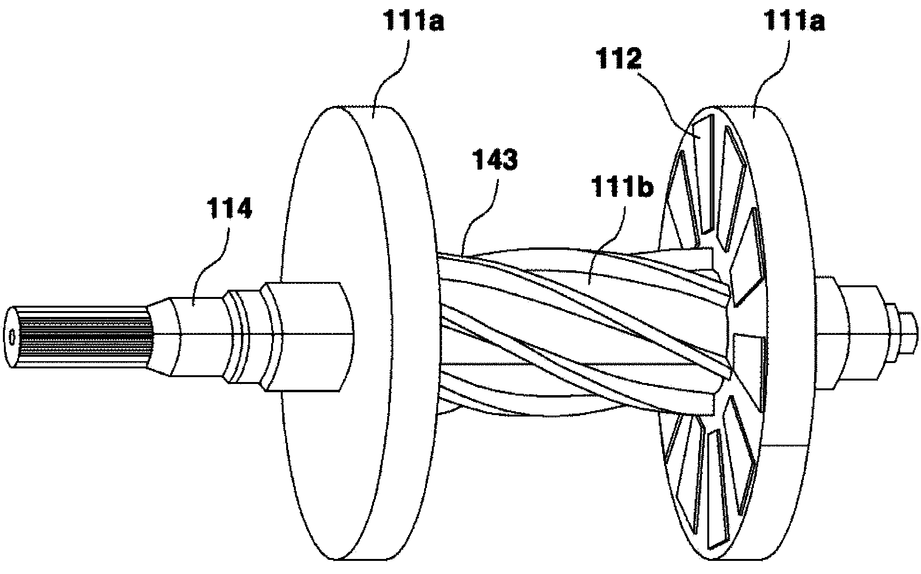
[0038] The rotor 110 may include a rotor case composed of a cylindrical base 111b connecting two bottom plates 111a arranged in parallel to each other, and one or more permanent magnets 112 embedded in the bottom plate 111a of the rotor case 111 .

[0039] The rotor 110 includes a rotating shaft 114 that transmits r...


PUM


Abstract

According to a rotor eccentricity preventing structure of the invention, on a motor which comprises a stator that includes a motor housing of which an iron core that is coiled by a coil is jointed, and a rotor which comprises a permanent magnet that rotates through an electromagnetic field generated by the coil and a rotating shaft, a bearing which supports the rotor to rotate is movably mounted on the motor housing. According to the rotor eccentricity preventing structure provided by the invention, eccentricity of the motor rotor can be prevented and a clearance between the rotor and the stator is kept even when thermal expansion occurs on the rotating shaft of an axial flux motor.

Description

technical field [0001] The present invention relates to a structure for preventing rotor eccentricity, in particular to a structure for preventing rotor eccentricity which prevents rotor eccentricity caused by thermal expansion of a rotating shaft of a motor mounted on a vehicle such as an electric vehicle. Background technique [0002] Currently, research and development activities are active on hybrid vehicles or electric vehicles, which are another form of vehicles that are environmentally friendly and consider fuel efficiency, which are further developed from vehicles using combustion engines. [0003] A hybrid vehicle combines the existing engine with an electric motor driven by electric energy, and drives the vehicle with two power sources. Electric vehicles are only driven by electric motors, thereby reducing environmental pollution caused by exhaust gas and improving fuel efficiency. However, it is popular in the United States and Japan, and it is gradually attractin...

Claims


Application Information

Patent Timeline
IPC IPC(8): H02K5/173H02K1/32
CPCY02T10/641Y02T10/64H02K5/04H02K7/083H02K1/2793H02K7/003H02K7/04H02K21/24B60K2001/006B60Y2200/90
Inventor 金尚真
Owner HYUNDAI MOBIS CO LTD
Learn More