A direct spray motor cooling system

A motor cooling and spraying technology, which is applied in the direction of cooling/ventilation devices, electrical components, electromechanical devices, etc., can solve the problems of lower rigidity of the casing and expensive heat pipes, and achieve high insulation, enhanced cooling effect, and volatility small effect

Active Publication Date: 2016-08-17
SOUTH CHINA UNIV OF TECH
View PDF6 Cites 0 Cited by
  • Summary
  • Abstract
  • Description
  • Claims
  • Application Information

AI Technical Summary

Problems solved by technology

However, the heat pipe is expensive and it is difficult to cool the rotor winding, because it needs to dig holes in the casing or stator, and the rigidity of the casing will be reduced

Method used


Image

  • A direct spray motor cooling system
  • A direct spray motor cooling system
  • A direct spray motor cooling system

Examples


Embodiment 1

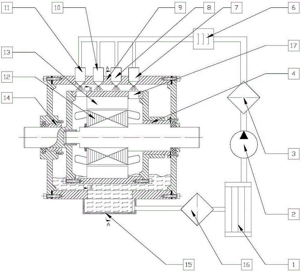
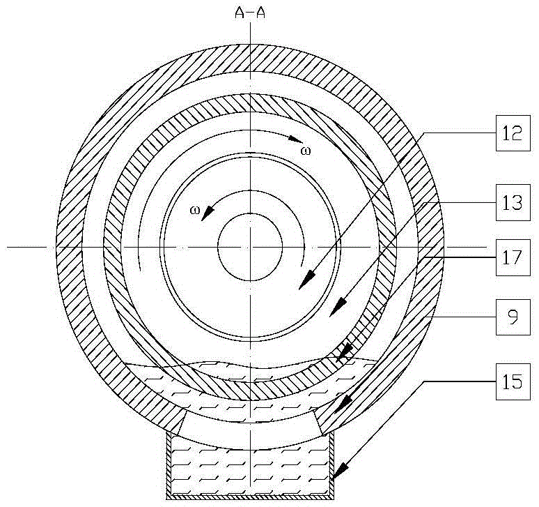
[0027] The counter-rotating double-rotor motor is a new type of electric drive system. It has no stator, and the inner and outer rotors rotate in different directions and output power to both sides respectively. Because the armature winding is rotating and has power output on both sides, it is difficult for traditional air-cooled and water-cooled systems to effectively cool the winding. This embodiment can well solve this problem.

[0028] Such as Figure 1-3 As shown, a direct spray motor cooling system is applied to the cooling of counter-rotating dual-rotor motors. The direct spray motor cooling system includes a radiator 1, an oil pump 2, a fine filter 3, a dryer 6, a nozzle, an oil pan 15, and a coarse filter 16; there are multiple nozzles, namely the first nozzle 7 and the second nozzle 8. The third nozzle 10 and the fourth nozzle 11; the radiator 1, the oil pump 2, the fine filter 3 and the dryer 6 are connected in sequence through pipelines, and the dryer 6 is connec...

Embodiment 2

[0035] The motor in this embodiment has an outer stator and inner rotor structure, and the composition of the direct spray motor cooling system in this embodiment is basically the same as that in Embodiment 1.

[0036] Figure 4 , Figure 5 Shown is another embodiment of the invention. Such as Figure 4 , 5As shown, a direct spray motor cooling system is applied to motor cooling with an outer stator inner rotor structure. The direct spray motor cooling system includes a radiator 1, an oil pump 2, a fine filter 3, a dryer 6, a nozzle, an oil pan 15, and a coarse filter 16; there are multiple nozzles, namely the first nozzle 7 and the second nozzle 8. The third nozzle 10 and the fourth nozzle 11; the radiator 1, the oil pump 2, the fine filter 3 and the dryer 6 are connected sequentially through pipelines, and the dryer 6 is connected with multiple nozzles through pipelines; The oil pan 15 is connected to the coarse filter 16 , and the coarse filter 16 is connected to the r...

Embodiment 3

[0039] The motor in this embodiment has an outer rotor and inner stator structure, and the composition of the direct spray motor cooling system in this embodiment is basically the same as that in Embodiment 1.

[0040] Figure 6 , Figure 7 Shown is a third embodiment of the invention. Such as Figure 6 , 7 As shown, a direct spray motor cooling system is applied to motor cooling with an outer rotor inner stator structure. The direct spray motor cooling system includes a radiator 1, an oil pump 2, a fine filter 3, a dryer 6, a nozzle, an oil pan 15, and a coarse filter 16; there are multiple nozzles, namely the first nozzle 7 and the second nozzle 8. The third nozzle 10 and the fourth nozzle 11; the radiator 1, the oil pump 2, the fine filter 3 and the dryer 6 are connected sequentially through pipelines, and the dryer 6 is connected with multiple nozzles through pipelines; The oil pan 15 is connected to the coarse filter 16 , and the coarse filter 16 is connected to the ...


PUM


Abstract

The invention discloses a direct spray-type motor cooling system which comprises a radiator, an oil pump, a fine filter, a drier, nozzles, an oil sump and a coarse filter. There are a plurality of nozzles. The radiator, the oil pump, the fine filter and the drier are successively connected through pipelines. The drier is connected with the plurality of nozzles through pipelines. The plurality of nozzles are arranged on a motor shell. At least one nozzle is communicated with an internal rotor or stator on the inner side of a motor, and at least another nozzle is directly facing a stator or rotor shell on the outside of the motor. The inner end at the bottom of the motor shell is provided with the oil sump which is connected with the coarse filter. The coarse filter is connected with the radiator. According to the invention, a motor stator (rotor) winding can be directly sprayed with a cooling medium, and the type of the motor and the position of the rotor are unlimited. The cooling medium can be used to lubricate rolling bearings or sliding bearings in the motor. Thus, the motor winding can be cooled effectively, and cooling and lubrication system integration of the motor also can be realized. The system provided by the invention has advantages of low cost, good cooling effect and the like.

Description

technical field [0001] The invention relates to a motor cooling system, in particular to the motor cooling system working in the manner of directly spraying cooling medium to the stator (rotor) of the motor. Background technique [0002] With the increasing tension of fossil energy and environmental problems, electric vehicles are getting more and more attention. In order to meet the driving requirements of electric vehicles, the driving motor needs to have a higher power density, which will make the motor heat more serious. Therefore, an efficient motor winding cooling solution has become an urgent need for the development of electric vehicle driving motors. [0003] At present, the cooling methods of motor windings are mainly air cooling and circulating water cooling. The cooling effect of air cooling increases as the fan speed increases, but the higher the fan speed, the greater the resistance, which will reduce the overall efficiency of the motor and easily cause vibrat...

Claims


Application Information

Patent Timeline
Patent Type & Authority Patents(China)
IPC IPC(8): H02K9/19H02K5/20
Inventor 罗玉涛
Owner SOUTH CHINA UNIV OF TECH
Why Eureka
Try Eureka