Ring-shaped oscillation circuit, ring-shaped oscillator and realization method thereof

A ring oscillator circuit and ring oscillator technology, applied in the field of telecommunications, can solve the problems of high design difficulty and high device precision, and achieve the effect of low power consumption and low power consumption

Active Publication Date: 2014-03-26
STATE GRID CORP OF CHINA +1
View PDF6 Cites 22 Cited by
  • Summary
  • Abstract
  • Description
  • Claims
  • Application Information

AI Technical Summary

Problems solved by technology

[0005] In order to solve the technical problems of the prior art ring oscillating circuit in order to achieve the purpose of temperature compensation and power supply voltage compensation, resulting in high precision requirements for devices and relatively difficult design, the present invention provides a ring oscillating circuit, a ring oscillator and its implementation method

Method used


Image

  • Ring-shaped oscillation circuit, ring-shaped oscillator and realization method thereof
  • Ring-shaped oscillation circuit, ring-shaped oscillator and realization method thereof
  • Ring-shaped oscillation circuit, ring-shaped oscillator and realization method thereof

Examples


Embodiment 1

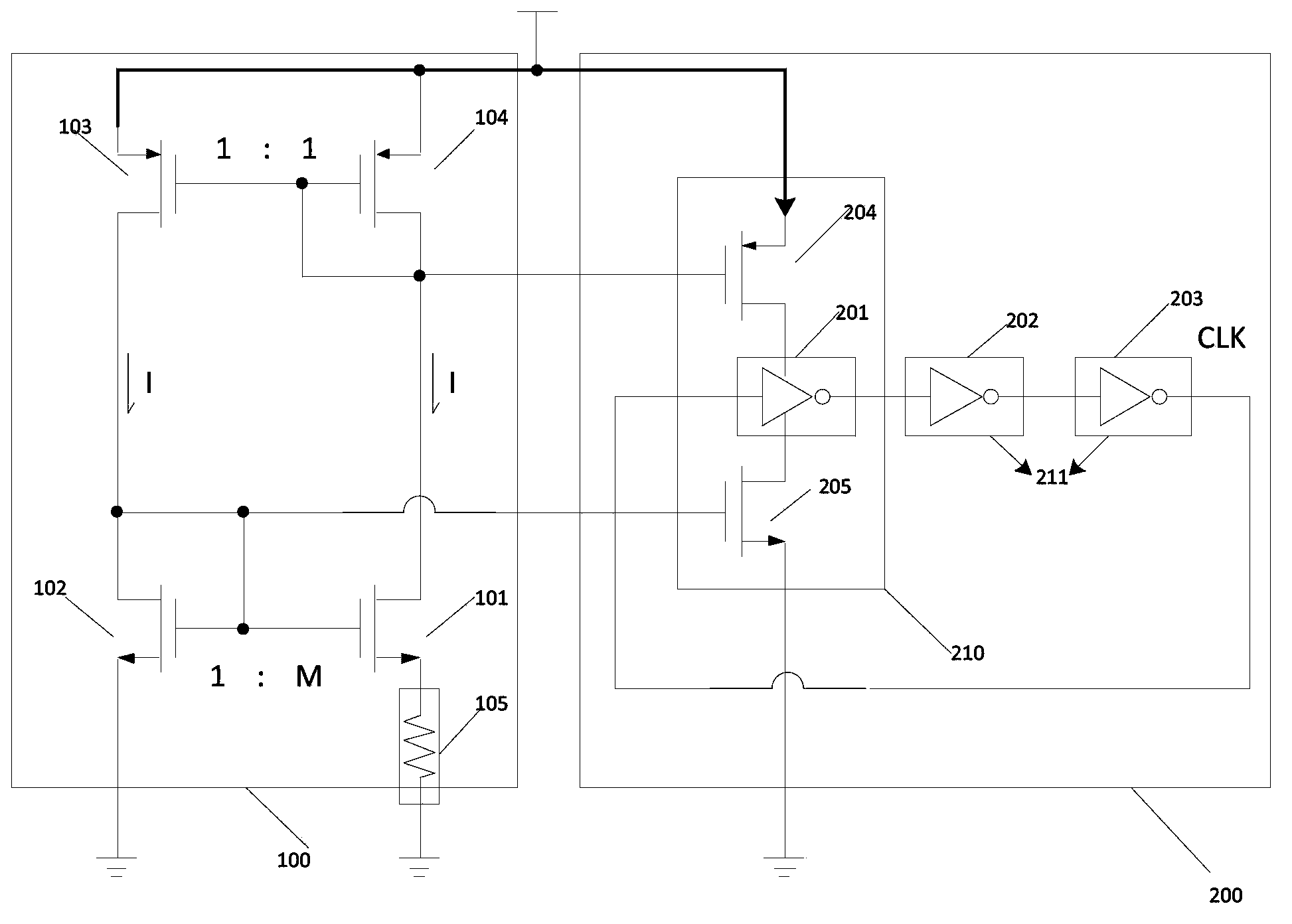
[0030] This embodiment provides a ring oscillator circuit, which includes: a current bias generation circuit 100 and a ring oscillator stage circuit 200;

[0031] The ring oscillator stage circuit 200 includes at least one stage of a first-type inverter 210 and at least one stage of a second-type inverter 211; wherein, the first-type inverter 210 is functionally used to limit current and belongs to is a current-limited inverter; the second inverter 211 includes a CMOS inverter.

[0032] The current bias generating circuit 100 is coupled with the first type inverter 210; the output end of the first type inverter 210 is connected with the input end of the second type inverter 211, and the output end of the second type inverter 211 It is connected with the input end of the first inverter 210 .

[0033] Wherein, in order to provide the first type of inverter 210 with a current that has no relation to the power supply voltage and has a positive temperature coefficient, the current...

Embodiment 2

[0055] This embodiment provides a ring oscillator. The ring oscillator includes the ring oscillator circuit described in Embodiment 1, and the specific content of the ring oscillator is not repeated here.

Embodiment 3

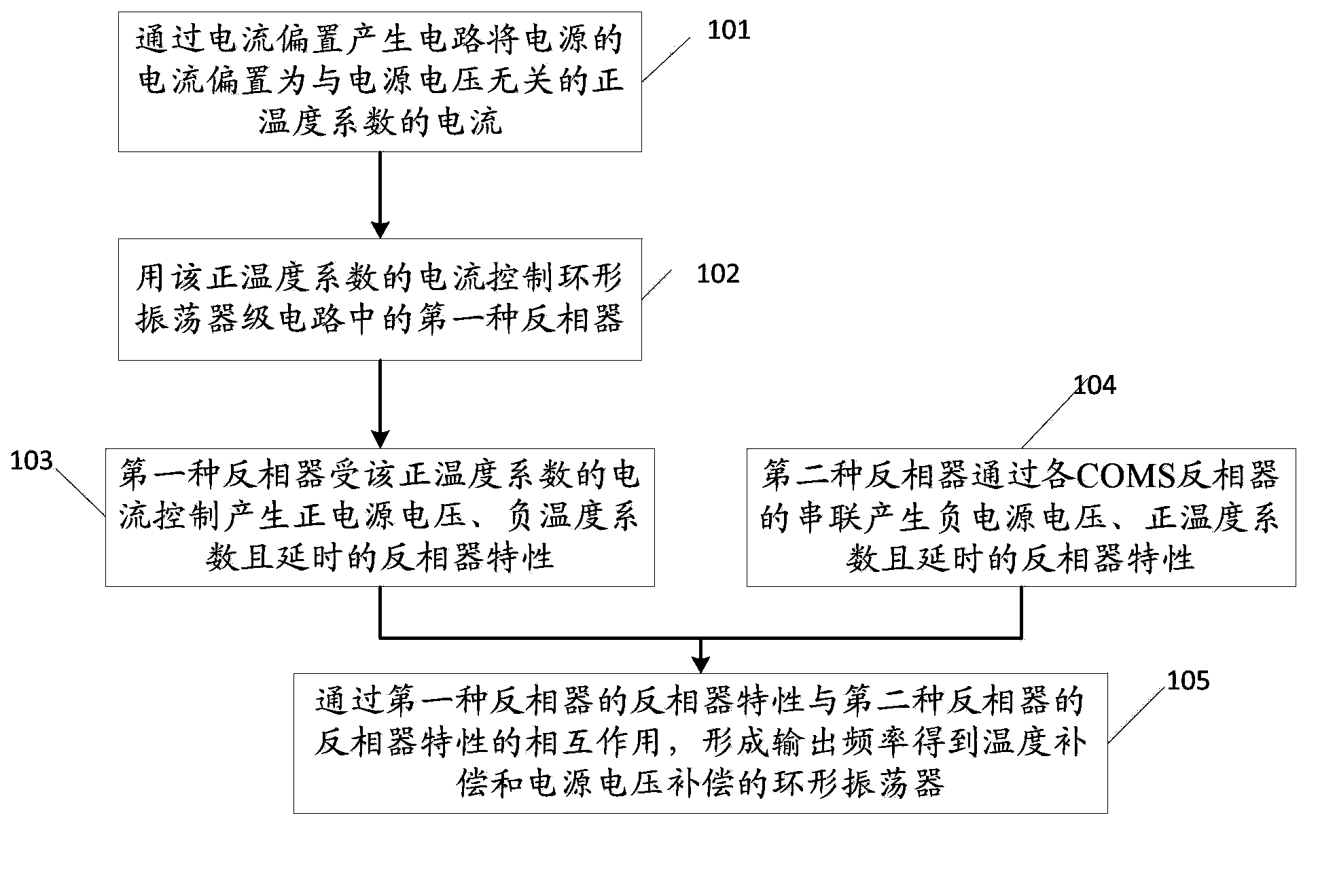
[0057] This embodiment provides a method for implementing a ring oscillator, such as figure 2 shown, including:

[0058] Step 101, using the current bias generation circuit to bias the current of the power supply to a current with a positive temperature coefficient independent of the power supply voltage;

[0059] Step 102, using the positive temperature coefficient current to control the first inverter in the ring oscillator stage circuit;

[0060] Step 103, the first type of inverter is controlled by the positive temperature coefficient current to generate a positive power supply voltage, a negative temperature coefficient and a time-delayed inverter characteristic;

[0061] Step 104, at the same time that the inverter characteristics are generated in step 103, the second type of inverter generates negative power supply voltage, positive temperature coefficient and time-delayed inverter characteristics through the series connection of each COMS inverter;

[0062] Step 105...


PUM


Abstract

The invention discloses a ring-shaped oscillation circuit, a ring-shaped oscillator and a realization method thereof, relating to the technical field of telecommunications. A technical problem that the required precision of a ring-shaped oscillation circuit device is high in the prior art is solved. The circuit comprises a current bias generating circuit and a ring-shaped oscillator level circuit. The ring-shaped oscillator level circuit comprises at least one level of first type of inverter and at least one level of second type of inverter. The current bias generating circuit is coupled with the first type of inverter. The output end of the first type of inverter is connected with the input end of the second type of inverter. The output end of the second type of inverter is connected with the input end of the first type of inverter.

Description

technical field [0001] The invention relates to the technical field of telecommunication, in particular to a ring oscillator circuit, a ring oscillator and a realization method thereof. Background technique [0002] For most SOC (System on a Chip, system-on-a-chip) designs, the oscillator is an essential component, which can provide the clock for the chip. Among various types of oscillators, the ring oscillator does not require an external crystal or an inductor-capacitor tuning circuit, but only needs to use an odd number of inverters in series, and the output of the last stage is connected to the input of the first stage. can work. Considering its simple structure and low power consumption, ring oscillators are widely used in occasions where frequency accuracy is not required. However, the power supply voltage and ambient temperature have great influence on the output frequency of the ring oscillator. Therefore, the ring oscillator cannot meet the requirements of higher ...

Claims


Application Information

Patent Timeline
Patent Type & Authority Applications(China)
IPC IPC(8): H03K3/011
Inventor 王小曼原义栋何洋王于波唐晓柯
Owner STATE GRID CORP OF CHINA
Why Eureka
Try Eureka