Switching and dimming LED driving circuit

An LED driver and circuit technology, applied in the field of LED lighting, can solve problems such as inconvenient dimming methods, achieve cost and convenience advantages, and be easy to use widely.

Active Publication Date: 2014-03-26
SHANGHAI YAMING LIGHTING
View PDF4 Cites 17 Cited by
  • Summary
  • Abstract
  • Description
  • Claims
  • Application Information

AI Technical Summary

Problems solved by technology

[0003] In view of the shortcomings of the prior art described above, the purpose of the present invention is to provide a switch dimming LED drive circuit for solving the inconvenient defect of the existing LED dimming method

Method used


Image

  • Switching and dimming LED driving circuit
  • Switching and dimming LED driving circuit
  • Switching and dimming LED driving circuit

Examples


Embodiment Construction

[0027] Embodiments of the present invention are described below through specific examples, and those skilled in the art can easily understand other advantages and effects of the present invention from the content disclosed in this specification. The present invention can also be implemented or applied through other different specific implementation modes, and various modifications or changes can be made to the details in this specification based on different viewpoints and applications without departing from the spirit of the present invention.

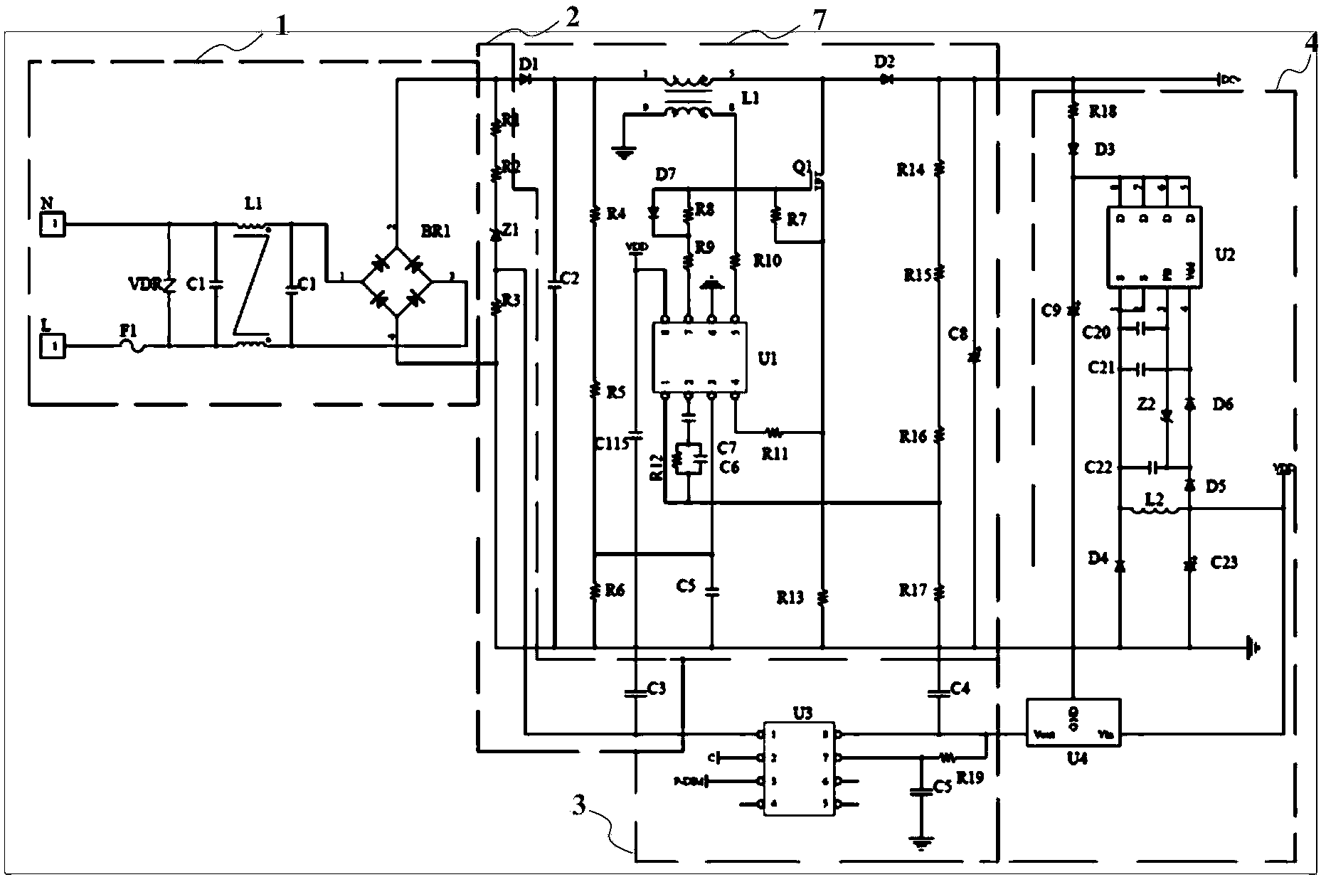
[0028] see figure 1 , The present invention provides a switch dimming LED drive circuit, including: filter rectification and EMI circuit 1, power on and off detection circuit 2, power switch counting and timing circuit, dimming control signal generation circuit, power factor circuit 7, power supply circuit 4. LED constant current drive circuit with dimming circuit. It should be noted that, in this embodiment, the power switch countin...


PUM


Abstract

The invention relates to a switching and dimming LED driving circuit which comprises a power supply switching counting and timing circuit. The power supply switching counting and timing circuit calculates on-off times and time of an input alternating-current power supply, namely a mains supply; signals are distinguished whether to be normal switching signals or dimming control signals, if the signals are the dimming control signals, output current value regulation is performed on a driving part of an LED, and a corresponding PWM (pulse width modulation) signal or reference voltage value is generated and given to the LED constant-current driving circuit with a dimming circuit so as to realize dimming without changing any existing wiring and without a remote control. Moreover, the on-off times basically have no influence on service life and lumen flux maintenance of an LED light source. The switching and dimming LED driving circuit has great advantages in terms of cost and convenience, and is easy for wide use.

Description

technical field [0001] The invention relates to the technical field of LED lighting, in particular to a switch dimming LED drive circuit. Background technique [0002] LED lighting has begun to be widely used, which belongs to the new lighting trend of environmental protection and energy saving. Among the dimming methods of LED lighting, there are analog voltage control dimming, digital control dimming, infrared or wireless remote control dimming, potentiometer dimming However, some of these dimming methods need to change the existing wiring method, and some require an external remote controller, etc., which brings inconvenience to the application. Contents of the invention [0003] In view of the above-mentioned shortcomings of the prior art, the purpose of the present invention is to provide a switch dimming LED drive circuit for solving the inconvenient defect of the existing LED dimming methods. [0004] In order to achieve the above purpose and other related purposes...

Claims


Application Information

Patent Timeline
Patent Type & Authority Applications(China)
IPC IPC(8): H05B37/02
CPCY02B20/42Y02B20/40
Inventor 张绍军
Owner SHANGHAI YAMING LIGHTING
Why Eureka
Try Eureka