Plastic worm injection forming mold

An injection molding and worm technology, applied in the field of mold manufacturing, can solve the problems of low efficiency, difficult to guarantee precision, and high production cost, and achieve the effects of high transmission efficiency, high product precision, and short injection cycle.

Inactive Publication Date: 2014-04-02
SHENZHEN HISYM IND
View PDF5 Cites 7 Cited by
  • Summary
  • Abstract
  • Description
  • Claims
  • Application Information

AI Technical Summary

Problems solved by technology

[0004] 1. Use the lathe for turning processing. The turning worm has a wide range of processing and is not limited by the diameter. However, the efficiency of turning the worm is relatively low, and it is mainly used in single-piece and small-batch production.
Moreover, the processing quality mainly depends on the technical level of workers, the accuracy of machine tools and cutting tools. The size difference between single products is large, the accuracy is difficult to guarantee, and the cost is high. It is not suitable for mass production.
[0005] 2. Manufactured by injection mold, how to demould the plastic worm has been perplexing technicians in this technical field
At present, there are two methods in the mold manufacturing of plastic worms: one method is to set an appropriate number of sliders on the spiral surface of the worm for core-pulling and demoulding. This mold has a simple structure and can be used when the precision is low, but The splicing line left on the product when the sliders are matched will seriously affect the use of the product, and it is not suitable for high-precision products; another method is to use an integral worm sleeve on the spiral surface of the worm, and set the

Method used


Image

  • Plastic worm injection forming mold
  • Plastic worm injection forming mold
  • Plastic worm injection forming mold

Examples


Embodiment Construction

[0021] Below in conjunction with accompanying drawing and specific embodiment the present invention is described in further detail:

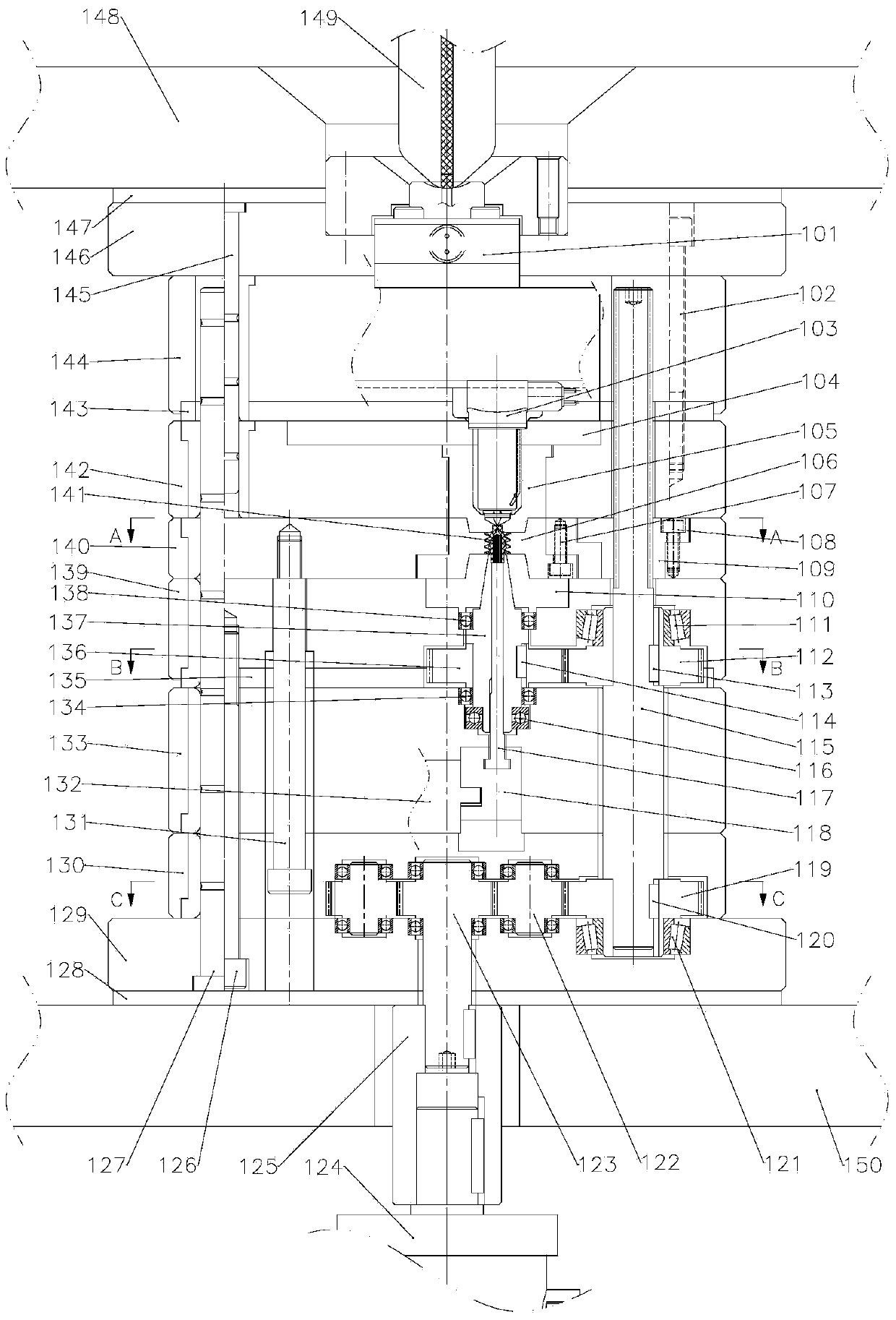
[0022] Such as figure 1 As shown, the plastic worm injection molding mold includes a fixed mold part and a movable mold part. The top plate 146 of the fixed mold part, the hot runner plate 144, and the fixed mold cavity plate 142 are fixedly connected with the fixed mold guide pillar 145 and the locking screw 102 in sequence, and the fixed mold cavity plate 142 center is provided with a fixed mold cavity 105, which is used for The fixed mold cavity pressing plate 104 is pressed and fixed on the fixed mold cavity plate 142 . The set hot runner system is placed in the fixed mold part, the sprue sleeve 101 of the hot runner system is connected with the nozzle 149 of the injection molding machine, and the outlet of the hot nozzle 103 of the hot runner system is connected with the worm cavity 141 . The heat insulation plate 147 fixed on the top pla...


PUM


Abstract

The invention provides a plastic worm injection forming mold. The worm injection forming mold comprises a stationary mold part and a movable mold part, wherein the stationary mold part comprises a demolding assembly consisting of a transmission mechanism and a sliding device; a stationary mold cavity of the stationary mold party, a worm cavity of the movable mold part, a movable mold cavity, and a movable mold insert are sequentially and tightly coupled to form a plastic worm cavity; an injection molding machine injects molten plastic in the worm cavity of the plastic worm mold through a hot runner system; the molten plastic is cooled and shaped to obtain the solid plastic worm. When demolding is performed, a hydraulic motor arranged in the injection molding machine and an oil cylinder arranged in the movable mold part drive the demolding assembly to separate the worm cavity and the molding insert from the plastic worm, and then the plastic worm can be taken down manually or by a manipulator. The mold is simple in structure, thin in the mold thickness, and capable of being mounted on a small precision injection molding machine to produce products. The product is excellent in various performances, high in precision, stable in size, short in production cycle and low in cost.

Description

technical field [0001] The invention relates to the field of mold manufacturing, in particular to a plastic worm injection molding mold. Background technique [0002] Plastic worms are widely used in modern industry. Plastic worms are often paired with worm gears to transmit motion and power between two staggered shafts. The worm transmission is equivalent to the screw transmission, which is a multi-teeth meshing transmission, so the transmission is stable and the noise is small. When the lead angle of the worm is smaller than the equivalent friction angle between the meshing teeth, the worm gear mechanism has a self-locking function. [0003] At present, the manufacture of plastic worms is mainly realized in the following two ways: [0004] 1. Use lathe for turning processing. The turning worm has a wide range of processing and is not limited by diameter. However, the efficiency of turning worm is relatively low, and it is mainly used in single-piece and small-batch produc...

Claims


Application Information

Patent Timeline
IPC IPC(8): B29C45/26B29C45/40
CPCB29C45/26B29C45/4005
Inventor 张海臣周庆胜
Owner SHENZHEN HISYM IND
Why Eureka
Try Eureka