Current transformer equipment with effects of self energy supply and low consumption and bus current detecting method

A current transformer and self-powered technology, which is applied in the direction of measuring current/voltage, instruments, voltage dividers, etc., can solve the problem of temperature, installation should be sensitive to light fluctuations, the overall power consumption of OCT is reduced, and the power consumption of voltage-frequency converters is large and other issues, to achieve the effect of simplifying circuit design, simple structure, and reducing power supply demand

Active Publication Date: 2014-04-02
SOUTHEAST UNIV
View PDF5 Cites 11 Cited by
  • Summary
  • Abstract
  • Description
  • Claims
  • Application Information

AI Technical Summary

Problems solved by technology

In the 1960s, a series of pure optical current and voltage transformers were developed by using the Pockels Effect and the Farady Effect. The method is direct, the device is simple, and the precision is high, but its disadvantages are : Sensitive to vibration, temperature, installation and light fluctuations, etc., poor measurement stability
In 2001, Huazhong University of Science and Technology proposed an OCT solution using Rogowski coils, integrators and voltage-frequency converters, using the traditional CT energy supply solution, but due to the large power consumption of the voltage-frequency converter, the overall power consumption of OCT Not significantly reduced
However, due to the influence of crystal nonlinearity and passive integration circuit, its actual accuracy is not ideal

Method used


Image

  • Current transformer equipment with effects of self energy supply and low consumption and bus current detecting method
  • Current transformer equipment with effects of self energy supply and low consumption and bus current detecting method
  • Current transformer equipment with effects of self energy supply and low consumption and bus current detecting method

Examples


Embodiment Construction

[0031] The technical solutions of the present invention will be described in detail below in conjunction with the accompanying drawings and embodiments.

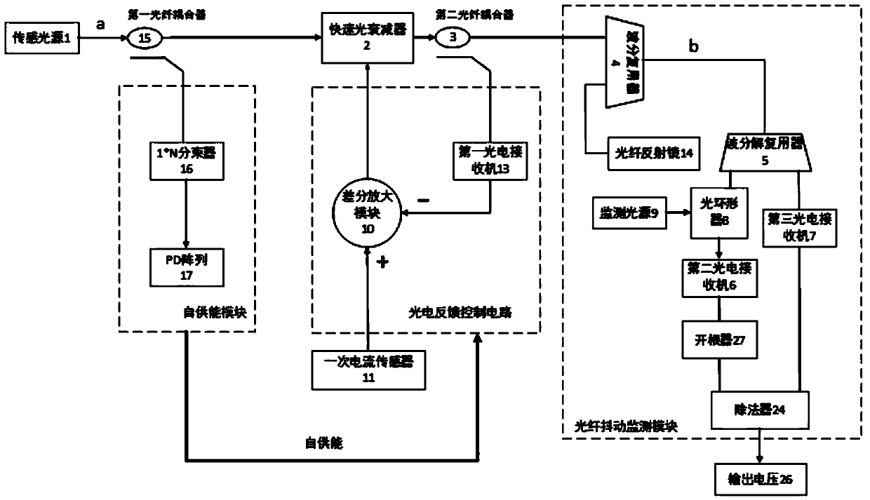
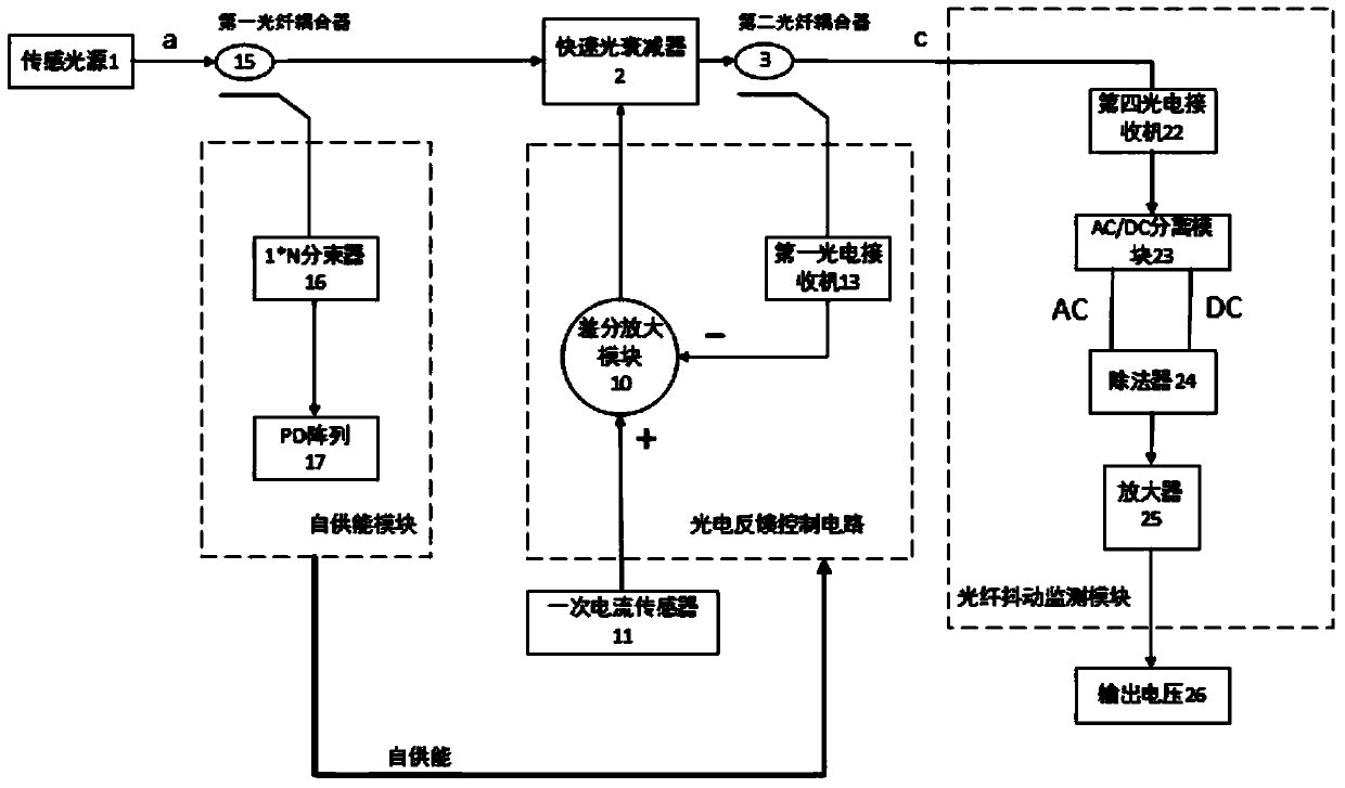
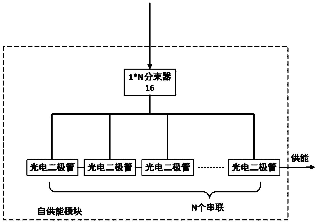
[0032] like figure 1 As shown, a current transformer device with self-supply and low power consumption of the present invention includes: a sensing light source 1, a fast tunable optical attenuator 2, a first optical fiber coupler 15 with a splitting ratio of m:n, and a splitting A second optical fiber coupler 3 with a ratio of p:q, a self-powered module, a photoelectric feedback control circuit, a primary current sensor 11 and an optical fiber jitter monitoring module. The output end of the sensing light source 1 is connected to the input end of the first optical fiber coupler 15, one output end of the first optical fiber coupler 15 is connected to the self-powered module, and the other output end of the first optical fiber coupler 15 is connected to the fast light attenuation 2 The optical input end of the fast tunable op...


PUM


Abstract

The invention discloses current transformer equipment with effects of energy self-supply and low consumption. The current transformer equipment comprises a sensing light source, a fast optical attenuator, a first optical fiber coupler, a second optical fiber coupler, an energy self-supply module, an optoelectrical feedback control circuit, a primary current sensor and an optical fiber jitter monitoring module, wherein the sensing light source is connected with the first optical fiber coupler, one output end of the first optical fiber coupler is connected with the energy self-supply module, the other output end of the first optical fiber coupler is connected with the fast optical attenuator, the electricity input end of the fast optical attenuator is connected with the optoelectrical feedback control circuit, the light output end of the fast optical attenuator is connected with the second optical fiber coupler, the output end of the second optical fiber coupler is connected with the optical fiber jitter monitoring module and the optoelectrical feedback control circuit, the optoelectrical feedback control circuit is connected with the primary current sensor, and the energy self-supply module is connected with the optoelectrical feedback control circuit. The current transformer equipment has the effects of energy self-supply and low consumption. The invention also provides a bus current detecting method which is high in measuring precision.

Description

technical field [0001] The invention belongs to the field of power system monitoring and protection, in particular to a current transformer device with self-supply and low power consumption and a bus current detection method. Background technique [0002] In the operation of power production, power transmission and power equipment, various physical quantities need to be monitored, among which the most important physical quantities are current and voltage. The sensor equipment that obtains current and voltage information is a transformer. High current or high voltage is converted to low current or low voltage on the low voltage side. Accurate, reliable and high-performance transformers are one of the important guarantees to ensure the safe, reliable and efficient operation of the power grid. [0003] Traditional transformers are mainly electromagnetic transformers, but their inherent shortcomings such as magnetic saturation, ferromagnetic resonance, small dynamic range, narr...

Claims


Application Information

Patent Timeline
Patent Type & Authority Applications(China)
IPC IPC(8): G01R15/04G01R19/00
Inventor 韦朴程澄孙小菡单雪康
Owner SOUTHEAST UNIV
Why Eureka
Try Eureka