
An ultra-precision scanning coating and positioning photolithography equipment

A technology of positioning light and fine scanning, which is applied in the direction of microlithography exposure equipment and photolithography exposure equipment, etc., can solve the problems of long processing cycle, large non-linear error error of graphics, complicated splicing process, etc., and achieve fast driving speed, The effect of improving efficiency and reducing costs

Active Publication Date: 2017-01-04
JIAXING HUALING MECHATRONICS CO LTD
View PDF11 Cites 0 Cited by
  • Summary
  • Abstract
  • Description
  • Claims
  • Application Information

AI Technical Summary

Problems solved by technology

The efficiency of the first-level micron-precision positioning process is low. In addition, due to the working stroke of piezoelectric ceramics, a mechanical splicing process is required to manufacture large-area high-precision dense gratings, and the mechanical splicing accuracy is poor and the splicing process is complicated. Therefore, Its processing cycle is long
CN1424594A discloses a laser direct writing device for manufacturing small-sized circular gratings, which is powerless for the manufacture of large-area high-precision gratings
Since the technology disclosed in this patent cannot be used for direct writing lithography, it is only limited to interference lithography, so the larger the grating area, the larger the interference pattern area and the size of the interference beam, and the errors caused by the nonlinear error of the pattern and the phase drift bigger

Method used


Image

  • An ultra-precision scanning coating and positioning photolithography equipment
  • An ultra-precision scanning coating and positioning photolithography equipment

Examples


Embodiment Construction

[0021] Specific embodiments of the present invention will be described below in conjunction with the accompanying drawings.

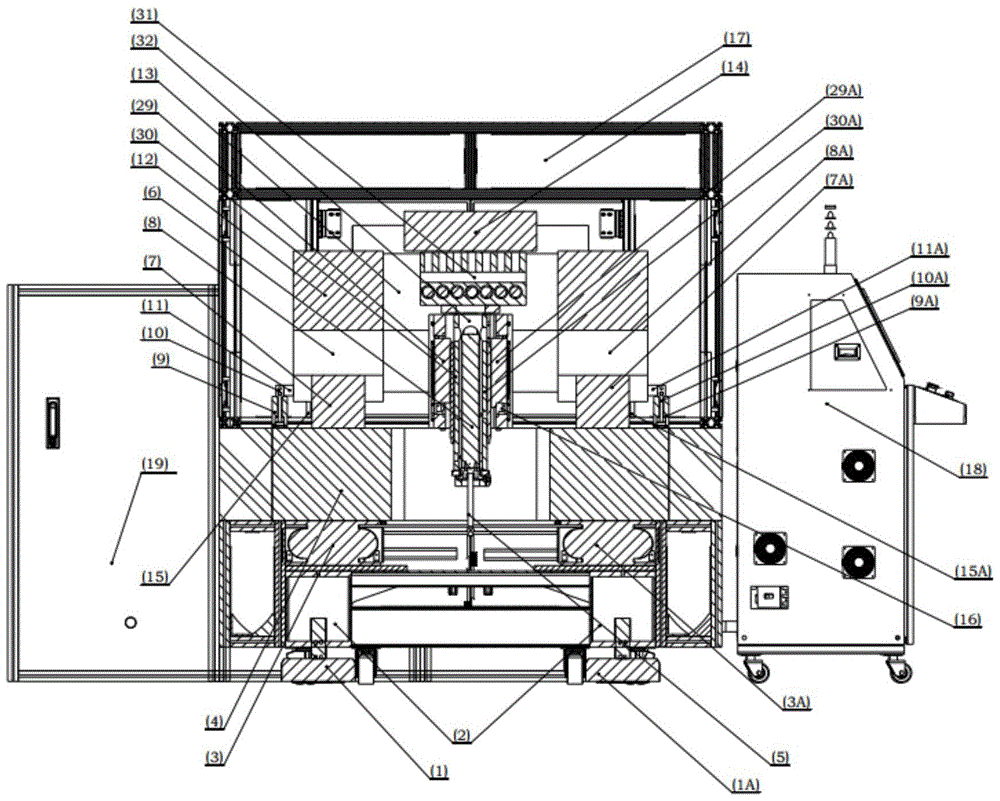
[0022] The levelness of the equipment can be adjusted through the leveling height step I1 and the leveling height step II1A set under the equipment support 2. The vibration damping system 3 is arranged on the upper part of the equipment support 2, and the granite base 4 is located on the low frequency air vibration damping system 3. The high-precision motion platform of the equipment is set on the precisely ground granite base 4, so that the vibration frequency of the high-precision motion platform is below 10Hz, eliminating the inherent vibration of the equipment and isolating the influence of the environment.

[0023] The cooling equipment and air filter equipment assembly 19 provides air sources for the air static pressure guide rail I7, the air static pressure guide rail II7A, the air static pressure slider I8, the air static pressure slider II8A and...


PUM


Abstract

The invention discloses an ultrahigh-precision scanning, film-coating, positioning and photo-etching device and belongs to the technical field of high-precision automatic etching devices. The ultrahigh-precision scanning, film-coating, positioning and photo-etching device comprises a vibration damping platform, a high-precision moving platform, a chemical glue coating or photo-etching processing box, a cooling device, an air pressure filtering device integrated body and a CNC (Computer Numerical Control) device, wherein the vibration damping platform is capable of eliminating the intrinsic vibration frequency of the device and avoiding influences by environment; the high-precision moving platform is driven by a great-thrust linear motor; a high-precision scanning motion and an ultrahigh-precision positioning motion of the linear motor provide support for uniform scanning and film coating, ultrahigh-precision positioning and photo-etching of the chemical glue coating or photo-etching processing box; the CNC device has a digital current servo control function, so that the high-precision moving platform and the chemical glue coating or photo-etching processing box work under the a clock signal. The device has film coating and photo-etching functions, so that production efficiency for manufacturing large-area optical gratings is improved, and cost of an optical grating manufacturing device is reduced.

Description

technical field [0001] The invention belongs to the technical field of high-precision automatic etching equipment, and in particular relates to a large-scale ultra-precision scanning coating and positioning photolithography equipment. Background technique [0002] Gratings are the core optical components in engineering systems such as optical systems and scientific instruments such as large astronomical telescopes, inertial confinement fusion laser ignition systems, and lithography systems. The size, line density and precision of the grating constrain the development of optical instrument systems, so the manufacture of large-area high-precision dense gratings has become a hot issue in the field of grating manufacturing. [0003] Common grating manufacturing methods include mechanical scribing, laser direct writing, and laser interferometry. CN102513878A discloses a kind of mechanical marking grating equipment. The nanoscale positioning workbench adopts the structure of inne...

Claims


Application Information

Patent Timeline
Patent Type & Authority Patents(China)
IPC IPC(8): G03F7/20
Inventor 伍鹏
Owner JIAXING HUALING MECHATRONICS CO LTD
Learn More