Switching power supply with testability function and testing method thereof

A switching power supply and function technology, applied in the field of power supply, can solve the problems of switching power supply not being testable, complicated manual test process, difficult maintenance and support, etc., to achieve the effect of improving the failure detection rate, reducing the difficulty of testing, and improving the life cycle.

Inactive Publication Date: 2014-04-02
HARBIN INST OF TECH
View PDF5 Cites 10 Cited by
  • Summary
  • Abstract
  • Description
  • Claims
  • Application Information

AI Technical Summary

Problems solved by technology

[0019] The purpose of the present invention is to solve the problems that the existing switching power supply does not have testability. When the power supply fails, there are many problems such as complicated manual test process, long test time, difficult maintenance guarantee, high maintenance cost, etc., and provides a testable Functional switching power supply and test method

Method used


Image

  • Switching power supply with testability function and testing method thereof
  • Switching power supply with testability function and testing method thereof
  • Switching power supply with testability function and testing method thereof

Examples


specific Embodiment approach 1

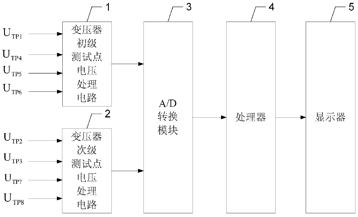
[0097] Specific implementation mode one: the following combination figure 1 , Figure 4 to Figure 7 Describe this embodiment, the switching power supply with testability function described in this embodiment, it includes auxiliary power supply, main power supply and test point voltage monitoring part, select test points TP1, TP2 and TP3 from the auxiliary power supply, from the main power supply Select the test points TP3, TP4, TP5, TP6, TP7 and TP8, the auxiliary power supply and the main power supply both include the transformer, where the test points TP1, TP4, TP5 and TP6 are taken from the primary side of the transformer, and TP2, TP3, TP7 and TP8 are taken from the The secondary side of the transformer; the voltage values ​​of the eight voltage monitoring points are U TP1 , U TP2 , U TP3 , U TP4 , U TP5 , U TP6 , U TP7 and U TP8 ; and is collected and processed by the voltage monitoring department of the test point;

[0098] The test point voltage monitoring part...

specific Embodiment approach 2

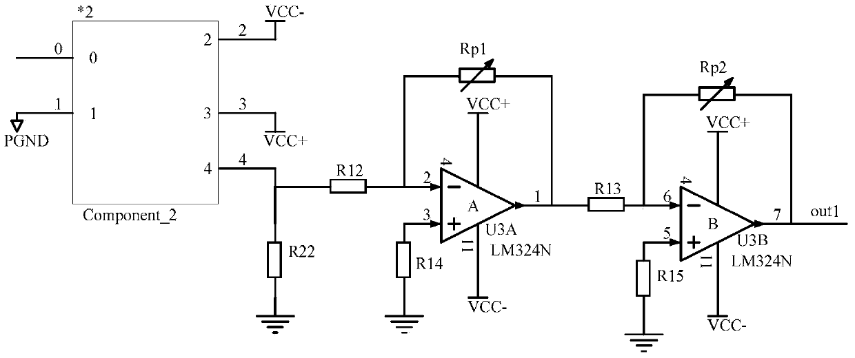
[0140] Specific implementation mode two: the following combination figure 2 Describe this embodiment, this embodiment will further explain the first embodiment, the transformer primary test point voltage processing circuit 1 includes a Hall sensor, a comparator A, a comparator B, a resistor R12, a resistor R13, a resistor R14, a resistor R15, and a resistor R22 , sliding rheostat Rp1 and sliding rheostat Rp2;

[0141] The input pin of the Hall sensor is connected to the voltage signal U of the test point TP1, TP4, TP5 or TP6 TP1 , U TP4 , U TP5 or U TP6 ;

[0142] The output pin of the Hall sensor is grounded through the resistor R22;

[0143] The output pin of the Hall sensor is also connected to the inverting input terminal of the comparator A through the resistor R12; the non-inverting input terminal of the comparator A is grounded through the resistor R14; the sliding rheostat Rp1 is connected in series between the inverting input terminal and the output terminal of ...

specific Embodiment approach 3

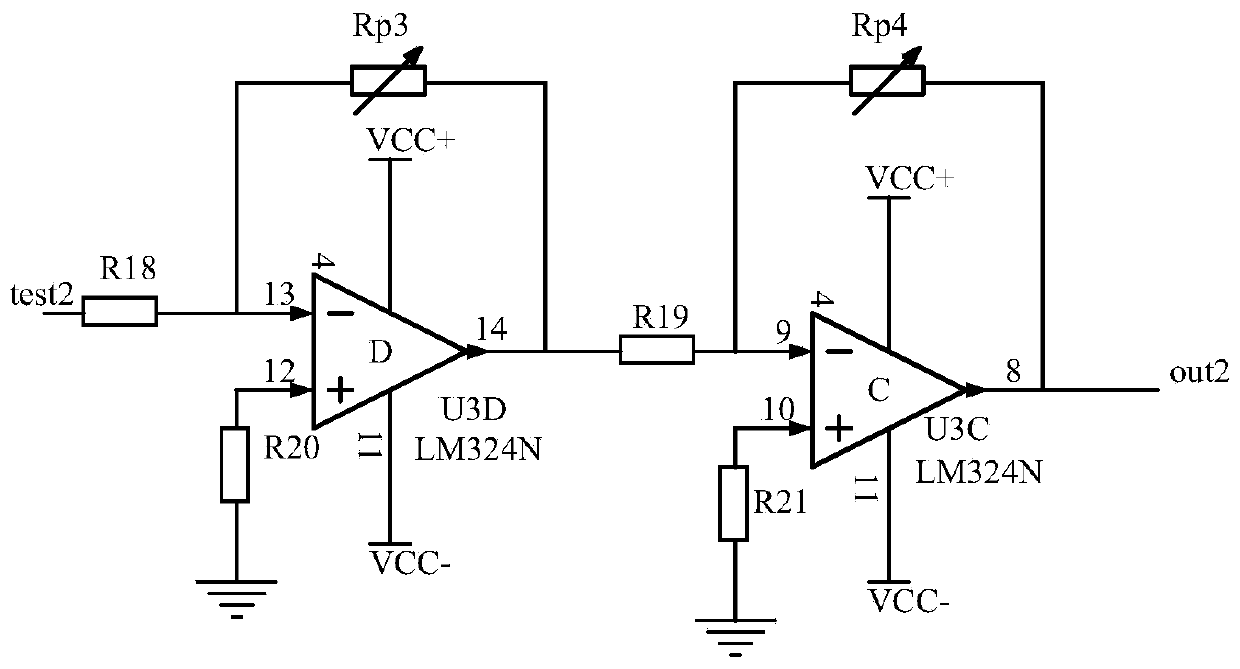
[0146] Specific implementation mode three: the following combination image 3 Describe this embodiment, this embodiment will further illustrate the first embodiment, the transformer secondary test point voltage processing circuit 2 includes a comparator C, a comparator D, a resistor R18, a resistor R19, a resistor R20, a resistor R21, a sliding rheostat Rp3 and a sliding Rheostat Rp4;

[0147] Voltage signal U of TP2, TP3, TP7 or TP8 TP2 , U TP3 , U TP7 or U TP8 The inverting input terminal of comparator D is connected through resistor R18; the non-inverting input terminal of comparator D is grounded through resistor R20, and the sliding rheostat Rp3 is connected in series between the output terminal of comparator D and the inverting input terminal; the output terminal of comparator D is passed through Resistor R19 is connected to the inverting input terminal of comparator C;

[0148] The non-inverting input terminal of comparator C is grounded through resistor R21, the s...


PUM


Abstract

The invention relates to a switching power supply with a testability function and a testing method thereof and belongs to the field of power supplies. The switching power supply with the testability function is used for solving the problems that during power failure, the manual testing process is complicated, the testing time is long, the maintenance support is difficult, the maintenance cost is high and the like caused due to the fact that the existing switching power supplies do not have testability. According to the switching power supply and the testing method thereof, the switching power supply is universal, eight test points are selected from the switching power supply, four test points are selected from the primary side of a transformer, four test points are selected from the secondary side of the transformer, eight voltages are processed and then are transmitted to a processor, judgment is carried out sequentially on TP4, TP5, TP1-TP2-TP3 (side by side in a group) and TP6-TP7-TP8 (side by side in a group), failure information is obtained easily and is displayed on a display, and then, maintenance personnel can quickly and accurately diagnose failure and isolate components and devices which are in failure, so that the workload of human judgment is reduced greatly.

Description

technical field [0001] The invention relates to a switching power supply with testability function and a testing method, belonging to the field of power supply. Background technique [0002] From the perspective of components, the types of failures can be divided into two categories: [0003] 1. Hard fault: refers to the open circuit or short circuit failure of components. [0004] 2. Soft faults: Refers to component parameter values ​​that exceed the tolerance range of components. Generally, they are not complete failure of equipment, such as component parameter changes due to aging, deterioration of components or changes in the use environment. Strictly speaking, the hard faults of components in the network have changed the topology of the network and made the circuit function invalid, while the soft faults of components will not cause changes in the network topology, but will only cause slight changes in circuit performance. Such a change usually does not have a signifi...

Claims


Application Information

Patent Timeline
Patent Type & Authority Applications(China)
IPC IPC(8): H02M1/00G01R31/40
Inventor 朱敏戴建卓陈曦顾大中王荔王天昊
Owner HARBIN INST OF TECH
Why Eureka
Try Eureka