Large-power boost circuit with high transformation ratio

A step-up circuit and high transformation ratio technology, applied in the direction of converting DC power input to DC power output, output power conversion devices, electrical components, etc. low grade issues

Active Publication Date: 2014-04-02
BEIJING MECHANICAL EQUIP INST
View PDF2 Cites 3 Cited by
  • Summary
  • Abstract
  • Description
  • Claims
  • Application Information

AI Technical Summary

Problems solved by technology

[0003] The purpose of the present invention is to provide a high-power and high-transformation-ratio booster circuit to solve the problems of the above-mentioned booster circuit with low power level, low energy utilization rate, and insufficient boosting capability

Method used


Image

  • Large-power boost circuit with high transformation ratio
  • Large-power boost circuit with high transformation ratio
  • Large-power boost circuit with high transformation ratio

Examples


Embodiment Construction

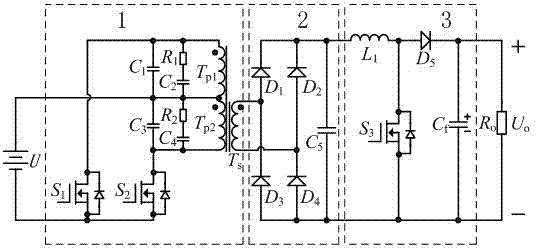
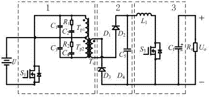
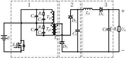
[0029] A high-power and high-transformation-ratio boost circuit includes: a front-stage push-pull boost sub-circuit 1, a rear-stage BOOST voltage-stabilizing sub-circuit 3, and an intermediate-stage resonant rectifier sub-circuit 2. The pre-stage push-pull boost sub-circuit 1 includes: the first power triode switch tube S 1 , the second power triode switch tube S 2 , the first primary winding T p1 , the second primary winding T p2 , the first absorption capacitor C 1 , the second absorption capacitor C 2 , the third absorption capacitor C 3 , the fourth absorption capacitor C 4 , the first snubber resistor R 1 , the second snubber resistor R 2 ; Intermediate resonant rectifier circuit 2, including: secondary winding T s , the first rectifier diode D 1 , second rectifier diode D 2 , the third rectifier diode D 3 , the fourth rectifier diode D 4 and resonant capacitor C 5 ; Post-stage BOOST voltage regulator sub-circuit 3, including: filter inductor ...


PUM


Abstract

The invention discloses a large-power boost circuit with a high transformation ratio. The large-power boost circuit comprises a pre-stage push-pull boost sub-circuit (1), a post-stage BOOST voltage stabilizing sub-circuit (3), and a mid-stage resonant rectifier sub-circuit (2). The large-power boost circuit adopts a two-stage cascade structure, wherein an output filter inductor of the pre-stage push-pull boost sub-circuit (1) and a filter inductor of the post-stage BOOST voltage stabilizing sub-circuit (3) share one inductor so as to reduce the circuit size and cost; a resonant capacitor C5 not only can form resonance together with leakage inductance refracted from a primary side to a secondary side to realize maximized energy transfer, but also can realize soft switching of a first power three-pole switch tube S1 and a second power three-pole switch tube S2 to further improve the circuit conversion efficiency.

Description

technical field [0001] The invention relates to a DC boost circuit, in particular to a high power and high transformation ratio boost circuit. Background technique [0002] At this stage, most of the airborne and vehicle power supply systems use DC 28V. In order to meet the needs of the subsequent electrical equipment, a high-efficiency boost circuit is usually added. At present, the DC boost circuit has a variety of structural forms, which are divided into single-ended flyback circuit, single-ended forward circuit, half-bridge circuit, full-bridge circuit, BOOST voltage regulator circuit and push-pull circuit according to the different connection methods of the power triode switch tube. Boost circuit. The characteristics of the indirect energy transmission of the single-ended flyback circuit and the single-phase limit operation of the transformer determine that it is only suitable for 100-200W low-power places; the single-ended forward circuit transformer is also single-ph...

Claims


Application Information

Patent Timeline
Patent Type & Authority Applications(China)
IPC IPC(8): H02M3/337
Inventor 赵鑫李力升李东昊杨帆
Owner BEIJING MECHANICAL EQUIP INST
Why Eureka
Try Eureka