A pulse d-type flip-flop using floating gate MOS tube

A MOS tube and flip-flop technology, which is applied in the field of pulse D-type flip-flops, can solve the problems of inferior performance such as speed and power consumption, and achieve the effects of higher power consumption, better speed, and better power consumption.

Inactive Publication Date: 2016-01-20
ZHEJIANG UNIV CITY COLLEGE
View PDF4 Cites 0 Cited by
  • Summary
  • Abstract
  • Description
  • Claims
  • Application Information

AI Technical Summary

Problems solved by technology

However, this flip-flop adopts a master-slave design scheme, which consists of two differential latches using multi-input floating gate MOS transistors, so the performance such as speed and power consumption is not as good as similar pulse flip-flops

Method used


Image

  • A pulse d-type flip-flop using floating gate MOS tube
  • A pulse d-type flip-flop using floating gate MOS tube
  • A pulse d-type flip-flop using floating gate MOS tube

Examples


Embodiment Construction

[0023] The present invention will be further described below in conjunction with the accompanying drawings and embodiments. While the invention will be described in conjunction with the preferred embodiments, it will be understood that it is not intended to limit the invention to the described embodiments. On the contrary, the invention is to cover alternatives, modifications and equivalents, which may be included within the scope of the invention as defined by the appended claims.

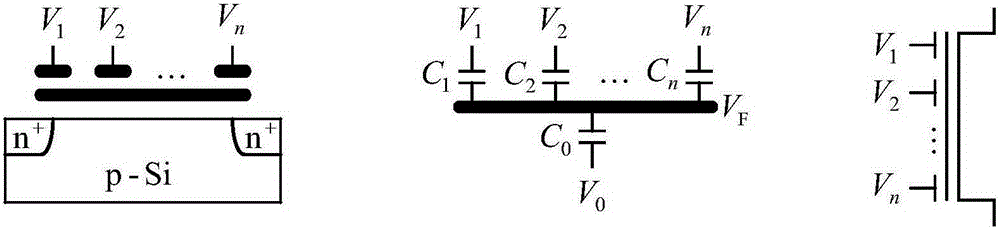
[0024] Such as image 3 As shown, this pulsed D-type flip-flop using a floating gate MOS transistor includes an inverter chain for inverting and delaying the clock signal, a pair of differentially configured pull-down multi-input floating gate MOS transistors, a pair of cross-coupled pMOS tube and two output inverters;

[0025] The inverter chain for inverting and delaying the clock signal is composed of inverters connected in series, including: a first inverter X1, a second inverter X2 and a th...


PUM


Abstract

The invention discloses a pulse D-type trigger adopting a floating gate MOS (Metal Oxide Semiconductor) pipe. The pulse D-type trigger comprises an inverter chain, two differential configuration pull-down multiple input floating gate MOS pipes, a pair of cross coupling pMOS pipes, and two output inverters, wherein the inverter chain is used for carrying out invert delay on a clock signal, and is formed by cascading three inverters; an on-off state of the two multiple input floating gate MOS pipes is controlled by the clock signal, a delay inversion signal of the clock signal, a data input signal, and an inversion signal of the data input signal, so that the data signal and the inversion signal thereof can be sampled within a narrower pulse width behind an edge of the clock signal; the pair of cross coupling pMOS pipes is used for latching a differential output signal; the two output inverters are used for buffering two complementary output end signals. The pulse D-type trigger has the beneficial effects that the pulse D-type trigger is simpler in structure, smaller in the number of adopted pipes, and better in speed and power consumption. In addition, since the number of the pipes connected into a traditional pull-down MOS pipe cascade network in series is reduced, the pulse D-type trigger can work under lower power voltage.

Description

technical field [0001] The invention relates to a pulse D-type flip-flop, more specifically, it relates to a pulse D-type flip-flop using a floating gate MOS tube. Background technique [0002] Flip-flops are the basic timing modules of digital systems, which have an important impact on the speed, power consumption, area and reliability of digital systems. Among many flip-flop structures, the flip-flop with differential structure has the characteristics of providing complementary dual-rail output at the same time, low power consumption and simple structure, etc., and has been valued. The edge trigger of the differential structure can adopt a master-slave design scheme or a pulse design scheme. The former consists of two stages of differential latches, while the latter consists of only a single latch. The pulse flip-flop drives the latch by generating a short pulse near the rising (falling) edge of the clock to sample the input data, which means that the input data can arri...

Claims


Application Information

Patent Timeline
Patent Type & Authority Patents(China)
IPC IPC(8): H03K3/356
Inventor 杭国强胡晓慧周选昌杨旸章丹艳尤肖虎
Owner ZHEJIANG UNIV CITY COLLEGE
Why Eureka
Try Eureka