Storage tank for fluids

A technology for storing containers and fluids, used in energy storage, indirect heat exchangers, heat exchanger types, etc., can solve problems such as power demand fluctuations, achieve shape optimization, minimize heat loss, and reduce container volume for a long time.

Inactive Publication Date: 2014-04-02
LINDE AG
View PDF6 Cites 0 Cited by
  • Summary
  • Abstract
  • Description
  • Claims
  • Application Information

AI Technical Summary

Problems solved by technology

[0006] It is known that one of the main challenges for efficient power generation by solar thermal power plants is the fl

Method used


Image

  • Storage tank for fluids
  • Storage tank for fluids

Examples


Embodiment Construction

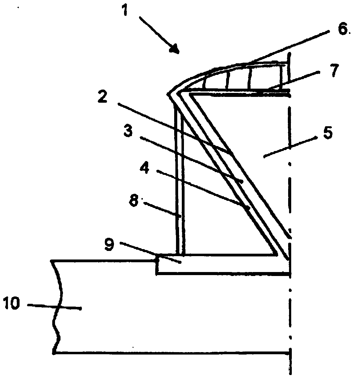
[0036] attached figure 1 In particular a storage container 1 is shown which has three shells 2 , 3 , 4 which are located one inside the other and which take the form of a right cone standing at the apex. The inner shell 2 is surrounded by a thermal insulation layer 3 which is in turn surrounded by an outer shell 4 . The interior of the inner shell is adapted to accommodate a thermal fluid 5 and is vertically delimited by a roof 6 with a suspended thermal insulation 7 . The housing 4 is supported by struts 8 on a base 9 which anchors the storage container to the ground 10 . In this embodiment, which is particularly advantageous for the invention, the inner shell 2 is shown as a right cone with an apex angle of approximately 70°. Preferably, in this embodiment, the housing 4 and the pillars 8 are designed as concrete structures.

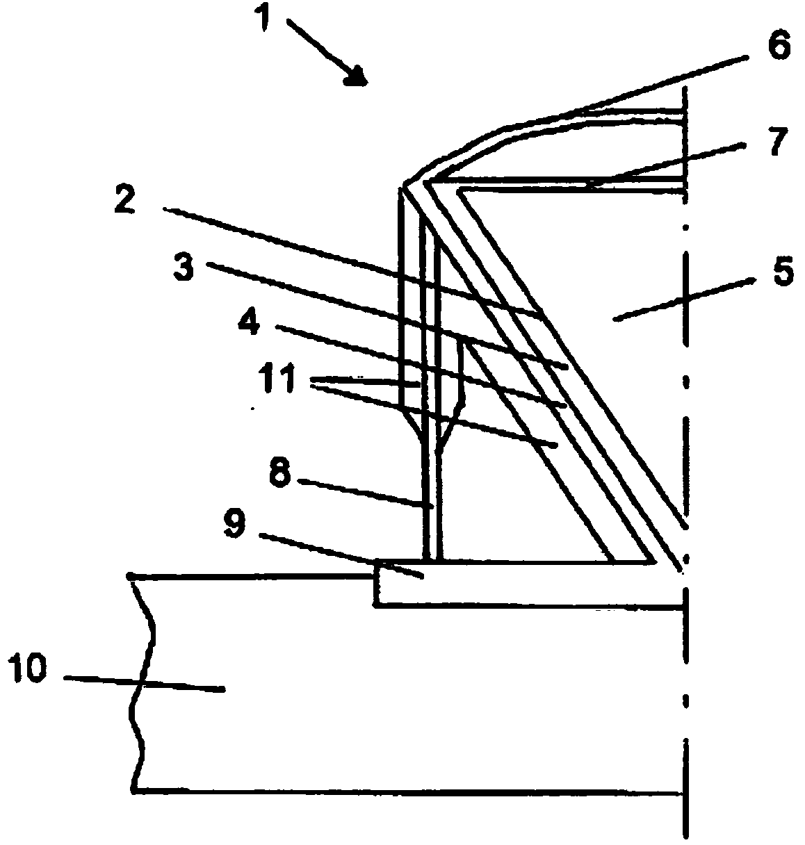
[0037] attached figure 2 A storage container 1 is shown having three shells 2, 3, 4 located one within the other and in the form of a right cone ...


PUM


Abstract

The invention relates to a storage tank (1) for holding a fluid (5) that has a temperature of at least 200 DEG C, said tank having an outer shell (4), an inner shell (2) and a thermal insulation layer (3) lying between said shells. The invention is characterised in that the inner shell (2) is designed in the form of a vertical inverted cone. The invention also relates to the use of a storage tank (1) of this type for storing energy in solar thermal power plants and for retrofitting in conventional storage tanks.

Description

technical field [0001] The invention relates to a storage vessel for containing a thermal fluid having a temperature of at least 200° C., the storage vessel having an outer shell, an inner shell and a thermal insulation layer between the outer shell and the inner shell. The invention further relates to the use of storage containers for energy storage in solar thermal power plants and the use for retrofitting conventional storage containers. Background technique [0002] Conventional storage vessels for holding thermal fluids such as liquid semiconductors or liquid salts usually have cylindrical vessel walls. The container wall is heated until it reaches the temperature of the thermal fluid stored in the storage container. Low alloy carbon steels can be used for vessel walls at temperatures up to 400°C. However, at higher temperatures, austenitic chromium-nickel steels must be used. Usually, the container wall is surrounded on the outside by thermal insulation. In the cas...

Claims


Application Information

Patent Timeline
IPC IPC(8): F28D20/00
CPCF28D2020/0047Y02E60/142Y02E70/30F28F2265/26F28F2270/00F28D20/0034F28F2265/14Y02E60/14
Inventor H·波塞尔特M·克罗尔H·克普夫
Owner LINDE AG
Why Eureka
Try Eureka