Moving Object Detection Device
A technology for detection devices and moving objects, applied in measuring devices, electromagnetic measuring devices, electric/magnetic position measurement, etc., can solve problems such as difficult to compare output signals
- Summary
- Abstract
- Description
- Claims
- Application Information
AI Technical Summary
Problems solved by technology
Method used
Image


Examples
no. 1 example
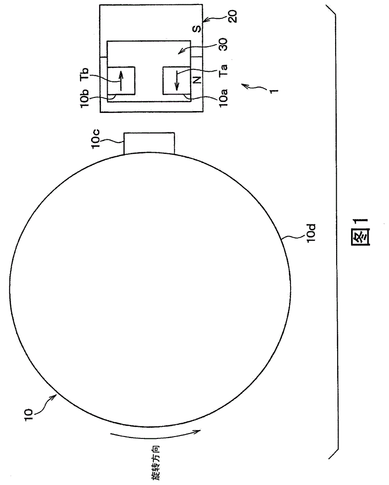
[0053] figure 1 The rotation detecting device 1 according to the first embodiment of the present disclosure is shown in . figure 1 is a view showing a schematic configuration of the rotation detection device 1 .
[0054] figure 1 The rotation detection device 1 shown in , detects the rotation of a spur gear 10 as a detection target by using TMRs 10a, 10b, and includes a bias magnet 20 and a circuit chip 30 in addition to the TMRs 10a, 10b.
[0055] The spur gear 10 is a rotor made of a magnetic material such as iron. The bias magnet 20 is a permanent magnet, and arranges the S pole and the N pole in line in the radial direction of the spur gear 10 (transverse direction in the figure). According to the present embodiment, the bias magnet 20 is oriented such that the N pole can face the outer peripheral portion of the spur gear 10 . For example, the bias magnet 20 is shaped like a substantially square plate.
[0056] The circuit chip 30 is a circuit board on which a rotatio...
no. 2 example
[0103] According to the second embodiment, a change in the characteristic representing the relationship between the magnetic flux density and the resistance of the TMRs 10a, 10b is corrected. Figure 7 The circuit configuration of the rotation detection device 1 according to the present embodiment is shown.
[0104] like Figure 7 shown, with figure 1 Compared with the rotation detecting device 1 shown in , the rotation detecting device 1 further includes resistive elements 11a, 11b.
[0105] The resistance element 11a is connected in parallel to the TMR10a between the transistor Tr3 and the ground. The resistance element 11b is connected in parallel to the TMR10b between the transistor Tr4 and the ground.
[0106] The combined resistance of the resistance element 11a and the TMR10a is hereinafter referred to as r1, and the combined resistance of the resistance element 11b and the TMR10b is hereinafter referred to as r2.
[0107] The resistance elements 11a, 11b are correc...
no. 3 example
[0112] According to the third embodiment, the change of the first current I1 flowing from the power supply Vdd to the transistors Tr1, Tr3 exhibits hysteresis with respect to the change of the magnetic flux density detected by the TMR10a. Figure 8 The circuit configuration of the rotation detection device 1 according to the present embodiment is shown.
[0113] like Figure 8 shown, compared to figure 1 In the rotation detection device 1 shown in FIG. 1 , the rotation detection device 1 further includes a variable resistance element 11 c , a resistance element 11 d and a control circuit 70 . The variable resistance element 11c is arranged in parallel to the TMR10a between the transistor Tr1 and the ground. The resistance element 11d is arranged in parallel to the TMR10b between the transistor Tr4 and the ground. According to the present embodiment, the maximum value Rmax of the variable resistance element 11c is set equal to the resistance of the resistance element 11d. T...
PUM
 Abstract
Description
Claims
Application Information