Supercharge Your Innovation With Domain-Expert AI Agents!

Method and device for analyzing amount of sludge and removing contaminants in high-temperature and high-turbidity water system flow trough

A technology of flow trough and turbid water, applied in separation method, feeding/discharging device of sedimentation tank, chemical instrument and method, etc., can solve the problem of increasing labor intensity of on-site cleaning workers, low degree of automation on site, and health of cleaning personnel. Harm and other problems, to achieve the effect of broad market application prospects, simple transformation, low equipment and operating costs

Inactive Publication Date: 2015-06-10
武汉钢铁有限公司
View PDF4 Cites 0 Cited by
  • Summary
  • Abstract
  • Description
  • Claims
  • Application Information

AI Technical Summary

Problems solved by technology

However, the elevated launder still has the following three deficiencies: 1. The sludge deposited in the launder has not been scientifically analyzed quantitatively, thus bringing great blindness and randomness to the manual cleaning of the launder; 2. The sludge deposited in the tank has certain toxicity, which will bring great harm to the health of the cleaning personnel; 3. There are a large number of scaling ions in the sludge deposited in the launder, which brings great harm to manual cleaning. Inconvenient, and the degree of automation at the work site is very low. The cleaning work is completely dependent on the pure manual work of the workers, which increases the labor intensity of the site cleaning workers and makes the labor cost very high.

Method used


Image

  • Method and device for analyzing amount of sludge and removing contaminants in high-temperature and high-turbidity water system flow trough
  • Method and device for analyzing amount of sludge and removing contaminants in high-temperature and high-turbidity water system flow trough
  • Method and device for analyzing amount of sludge and removing contaminants in high-temperature and high-turbidity water system flow trough

Examples


Embodiment Construction

[0035] Below in conjunction with accompanying drawing, invention is further explained:

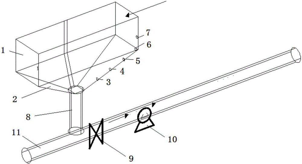
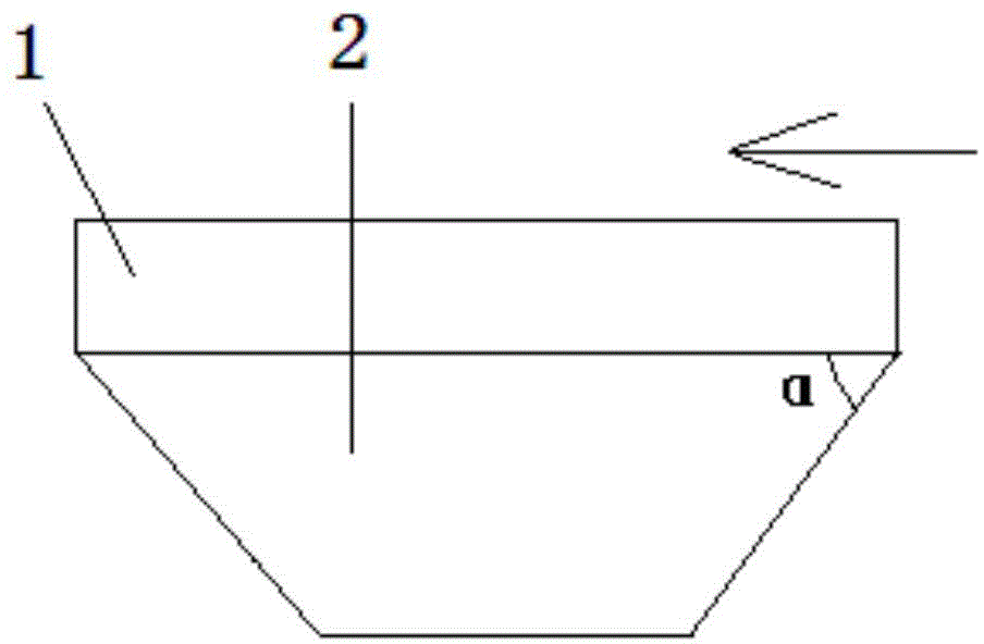
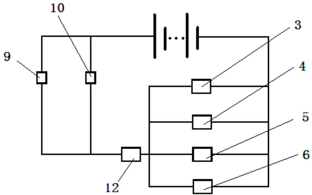
[0036] The concrete structure of device of the present invention sees figure 1 and figure 2 , the bottom of the launder 1 is provided with a cone bucket 2, and the angle a between the inclined wall of the cone bucket 2 and the bottom surface of the launder is 50-60 degrees. The bottom of the cone bucket 2 is connected to the sludge discharge pipe 11 provided with a mud discharge valve 9 and a mud pump 10 through a downcomer 8, and 4 electronic thermometers are evenly arranged on the side wall of the cone bucket 2 from bottom to top, Taking the vertical height h of the cone bucket 2 as the criterion, the four electronic thermometers are arranged from bottom to top on the side wall of the cone bucket. The electronic thermometer 5 at the height of 3 / 4h and the electronic thermometer 6 at the height of h are also provided with the electronic thermometer 7 on the trough at the same time, so ...


PUM


Abstract

The invention relates to a method and a device for analyzing the amount of sludge and removing contaminants in a high-temperature and high-turbidity water system flow trough, and solves the problems of blocking of an existing flow trough and difficulty in sludge removal. The device comprises a flow trough, wherein a conical hopper is arranged at the bottom of the flow trough; the bottom of the conical hopper is connected with a sludge discharging pipe with a sludge discharging valve through a downcomer; four electronic temperature meters are uniformly arranged on the side wall of the conical hopper from bottom to top. According to the method, the aim of automatically discharging the sludge is achieved by analyzing and comparing data measured through the electronic temperature meters at different vertical positions of the conical hopper, and analyzing the amount of the sludge. The method is simple and reliable, the contaminant removal effect is good, the amount of the sludge can be measured quantitatively, and the manual operation can be completely replaced. The device has time-saving, and labor-saving effects, is safe, reliable, long in service life, and capable of removing the contaminants without shutdown.

Description

technical field [0001] The invention relates to a method and device for sludge analysis and scale removal of sewage, in particular to a method and device for sludge analysis and scale removal in a launder of a high-temperature and high-turbidity water system. Background technique [0002] In the metallurgical industry, during the iron and steel production process, the flue gas from the top of the blast furnace or converter can be recycled into clean gas by washing with water. For the purpose of environmental protection and emission reduction, most metallurgical enterprises now purify the flue gas washing water for recycling. During this process, because a large amount of heat and solid impurities enter the water body when water and flue gas are in contact, the temperature of industrial sewage discharged after flue gas washing is relatively high, and the concentration of suspended solids and scaling ions is also very high. During the recycling process of turbid sewage, pipes...

Claims


Application Information

Patent Timeline
Patent Type & Authority Patents(China)
IPC IPC(8): B01D21/02B01D21/24B01D21/30
Inventor 周泳吴良玉颜斌段建峰肖凡李建梅杨明黄光辉
Owner 武汉钢铁有限公司
Features
  • R&D
  • Intellectual Property
  • Life Sciences
  • Materials
  • Tech Scout
  • Unparalleled Data Quality
  • Higher Quality Content
  • 60% Fewer Hallucinations
Learn More