
Vertical type pneumatic hanger

A crane and vertical technology, which is applied in the field of vertical pneumatic cranes, can solve problems such as hydraulic equipment blasting and affecting production, and achieve the effects of ensuring safe production, fast and reliable braking, and easy and flexible adjustments

Inactive Publication Date: 2014-04-09
WUJIANG JIA BILLION ELECTRONICS TECH
View PDF4 Cites 8 Cited by
  • Summary
  • Abstract
  • Description
  • Claims
  • Application Information

AI Technical Summary

Problems solved by technology

Most of the existing lifting equipment is hydraulic power equipment. Hydraulic equipment is generally in danger of blasting. According to national standards, there are explosion-proof requirements, otherwise production will be seriously affected.

Method used


Image

  • Vertical type pneumatic hanger

Examples


Embodiment Construction

[0023] The process embodiment will be described in detail below, so that the advantages and features of the present invention can be more easily understood by those skilled in the art, so as to define the protection scope of the present invention more clearly.

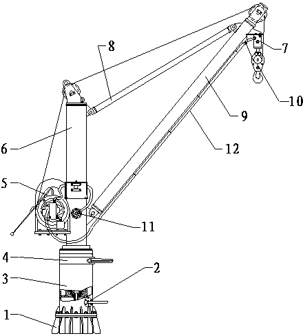
[0024] like figure 1 As shown in the structural diagram of the present invention, a vertical pneumatic crane includes a fuselage 3, an air source inlet 2 fixedly installed on one side of the fuselage 3, a rotating mechanism 4 installed on the fuselage 3, a fixed The frame 6 installed on the rotating mechanism 4, the gear box 5 installed on one side of the frame 6, the boom 9 rotatably installed on one side of the fuselage 3, and rotatably installed on the frame 6 The push rod 8 on the upper part and on the same side as the suspender 9, the hook 10 installed at the rotating end of the suspender 9, and the handle bar 12 passing through the bracket below the suspender 9, the push rod The rotating end of 8 is connected t...


PUM


Abstract

The invention provides a vertical type pneumatic hanger which comprises a body, a gas source inlet fixedly arranged on one side of the body, a rotating mechanism arranged on the body, a rack fixedly arranged on the rotating mechanism, a gearbox arranged on one side of the rack, a hanging rod rotationally arranged below one side of the body, a push rod rotationally arranged at the upper part of the rack and positioned on one same side in which the hanging rod is arranged, a hook arranged at one rotating end of the hanging rod, and a handle rod which penetrates through the bracket below the hanging rod, wherein the rotating end of the push rod is connected with the rotating end of the hanging rod. The hanger is free of anti-explosive requirements, and the problem of anti-explosion of crane equipment is thoroughly solved; energy is saved, and compressed air is adopted as the power, so that no medium is leaked, the environment pollution is prevented, and the sanitary production can be achieved; the continuous and frequent working is achieved, and the working is stable and reliable; the stepless speed regulation is achieved, and the operation speed is simply, conveniently and flexibly regulated through a manual valve; as a lifting mechanism is provided with an overload protection device, the normal operation of a speed reducer is ensured.

Description

technical field [0001] The invention relates to the field of mechanical equipment, in particular to a vertical pneumatic crane used for suspending and transporting heavy objects. Background technique [0002] Lifting equipment refers to electromechanical equipment used to carry or move heavy objects. Most lifting equipment starts a vertical or vertical and horizontal working stroke after retrieving the material. After reaching the destination, it is unloaded, and then travels empty to the reclaiming location to complete a working cycle, and then carry out the second lifting or handling. Generally speaking, when the lifting equipment is working, material retrieving, transportation and unloading are carried out in sequence, and the work of each corresponding mechanism is intermittent. Lifting equipment is mainly used to carry items, equipped with grab buckets to carry bulk materials such as coal, ore, and grain, and equipped with buckets to lift liquid materials such as molte...

Claims


Application Information

Patent Timeline
IPC IPC(8): B66C23/06B66C23/16B66C13/50B66C23/82
Inventor 陆全明
Owner WUJIANG JIA BILLION ELECTRONICS TECH
Learn More