Hoisting derrick specially for coiled tubing equipment

A derrick and equipment technology, applied to drilling equipment, support devices, earthwork drilling and production, etc., can solve the problems of high labor intensity in assembly and disassembly, unfavorable operation safety and alignment, time-consuming and labor-intensive problems, and reduce labor intensity and operating costs of workers , Improve work efficiency and safety, safe and simple operation

Inactive Publication Date: 2014-04-09
YANTAI JEREH PETROLEUM EQUIP & TECH CO LTD
View PDF11 Cites 119 Cited by
  • Summary
  • Abstract
  • Description
  • Claims
  • Application Information

AI Technical Summary

Problems solved by technology

If the vertical gantry derrick is used to lift the injection head, it is necessary to use crown blocks or hooks, etc., and the adjustment of the injection head and the wellhead position is very inconvenient; if the A-type derrick is used, because it is generally composed of multiple sections of derricks, it requires on-site assembly and disassembly. High strength, and working at heights is very dangerous, time-consuming and labor-intensive, and it is easy to cause damage to the rods during assembly and disassembly; due to damage, deformation, and loss of pipes, it is more difficult to install again, and transportation is inconvenient
There are also some movable derricks that can be used, but after the completion cycle of a well, they need to be completely dismantled, transported to a new well, and then reinstalled, which is time-consuming and laborious, and the work efficiency is low; if the injection head is lifted by a crane, the operator needs to Operating on the crane platform, the distance between the crane and the boom is short, remote control cannot be realized, and the operation is unsafe and inconvenient
In particular, it is inconvenient to move the injection head between a group of adjacent wellheads. Even if the injection head is moved to a new wellhead, it is difficult for the stretching direction of the coiled tubing to adapt to the tubing guide of the tubing drum.
In addition, it is difficult for the above-mentioned lifting equipment to ensure that the injection head can always be in a vertical position during the lifting process, which is not conducive to safe operation and alignment

Method used


Image

  • Hoisting derrick specially for coiled tubing equipment
  • Hoisting derrick specially for coiled tubing equipment
  • Hoisting derrick specially for coiled tubing equipment

Examples


Embodiment Construction

[0020] The principles and features of the present invention are described below in conjunction with the accompanying drawings, and the examples given are only used to explain the present invention, and are not intended to limit the scope of the present invention.

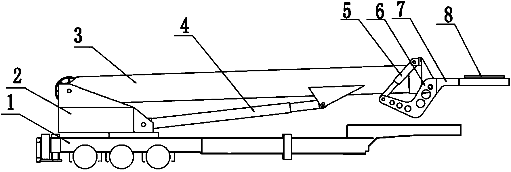
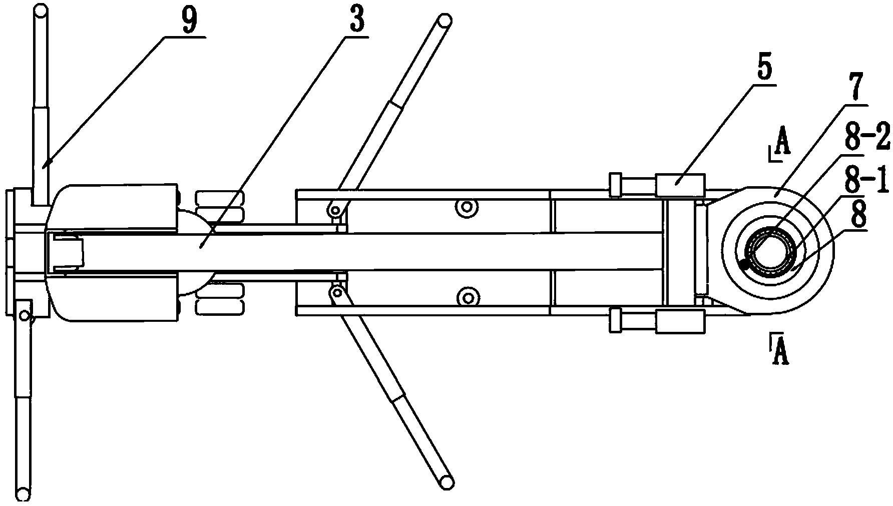
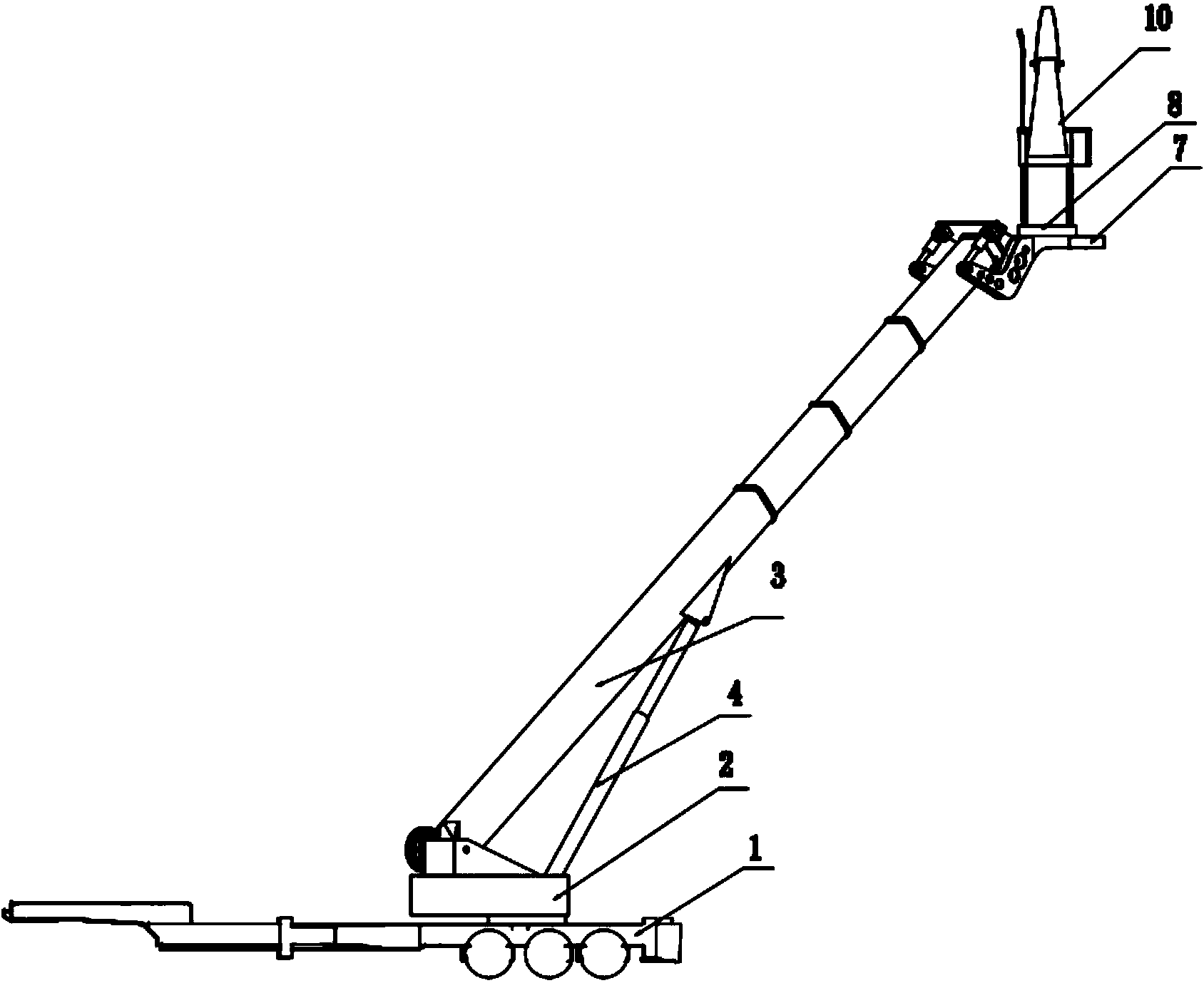
[0021] Such as Figures 1 to 6 As shown, a special hoisting derrick for coiled tubing equipment includes a derrick transport support platform 1, a derrick rotating base 2, a derrick telescopic arm 3, a first telescopic cylinder 4 and a second telescopic cylinder 5, and an injection head installation platform 7. The derrick rotary base 2 is connected to the derrick transport support platform 1 through a rotating mechanism, the lower end of the derrick telescopic arm is hinged to the derrick rotary base 2, the cylinder end of the first telescopic cylinder 4 and the plunger The ends are respectively hinged with the derrick rotary base 2 and the derrick telescopic arm 3; the injection head installation platform 7 is hin...


PUM


Abstract

The invention relates to a hoisting derrick specially for coiled tubing equipment. The hoisting derrick comprises a derrick transportation supporting platform, a derrick swinging base, a derrick telescopic boom, a first telescoping cylinder and second telescoping cylinders, which are connected with one another through rotation and articulation; the hoisting derrick is characterized by also comprising an injection head mounting platform, wherein lever arms are arranged on the injection head mounting platform, one ends of the level arms are fixedly connected with the injection head mounting platform, the other ends of the level arms are articulated with the plunger piston ends of the second telescoping cylinders, the cylinder body ends of the second telescoping cylinders are articulated with the derrick telescopic boom, and the level arms and the second telescoping cylinders are arranged in pairs and are arranged on two sides of the derrick telescopic boom respectively. The hoisting derrick has the beneficial effects that the injection head and an oil well can be centered rapidly, the labor intensity of workers is reduced and the mounting cost is reduced.

Description

technical field [0001] The invention relates to the field of oil drilling equipment, in particular to a hoisting derrick special for coiled tubing equipment. Background technique [0002] In the oilfield well site, it is often done to install the transshipment coiled tubing equipment. Due to the heavy weight of the coiled tubing injection head, it must be moved by lifting equipment. At present, the hoisting equipment commonly used in coiled tubing operations at home and abroad is portal derrick, tower derrick, A-type derrick, cranes, etc. If the vertical gantry derrick is used to lift the injection head, it is necessary to use crown blocks or hooks, etc., and the adjustment of the injection head and the wellhead position is very inconvenient; if the A-type derrick is used, because it is generally composed of multiple sections of derricks, it requires on-site assembly and disassembly. It is strong, and working at heights is very dangerous, time-consuming and labor-intensive...

Claims


Application Information

Patent Timeline
Patent Type & Authority Applications(China)
IPC IPC(8): E21B15/00
Inventor 李世奇王锋孙小丽丁文桂
Owner YANTAI JEREH PETROLEUM EQUIP & TECH CO LTD
Why Eureka
Try Eureka