
Method for controlling inlet air of turbo-charging gasoline engine

A technology of turbocharging and control methods, applied in engine control, mechanical equipment, combustion engines, etc., can solve the problems of large influence of human subjective factors, frequent valve opening and closing, long system development cycle, etc., to reduce workload, Guaranteed stability and strong usability

Inactive Publication Date: 2014-04-09
JILIN UNIV
View PDF6 Cites 23 Cited by
  • Summary
  • Abstract
  • Description
  • Claims
  • Application Information

AI Technical Summary

Problems solved by technology

[0004] 2. The conventional development process of ECU requires a lot of experience and calibration tests, the workload is heavy, the influence of human subjective factors is relatively large, and the system development cycle is long;
[0005] 3. The calibrated control algorithm has different anti-disturbance capabilities for factors such as parameter uncertainty
This method achieves boost control to a certain extent, but when the pressure value fluctuates up and down on the interference curve, the gas valve opens and closes too frequently

Method used


Image

  • Method for controlling inlet air of turbo-charging gasoline engine
  • Method for controlling inlet air of turbo-charging gasoline engine
  • Method for controlling inlet air of turbo-charging gasoline engine

Examples


Embodiment 1

[0152] This example preliminarily verifies the correctness and completeness of the control method of the present invention from the perspective of constant speed working conditions.

[0153] Parameter setting: Since the turbocharger can play its role in boosting torque better when the speed is high, the simulation environment is set to the dynamometer mode, so that the gasoline engine is at a constant speed of 4200rev / min, the simulation time is 13s, and the simulation step size is 0.01 s.

[0154] refer to Figure 7 to Figure 12 , the desired engine torque is Figure 12 The solid line shown in , according to the steps of the turbocharged gasoline engine air intake control method, the simulation experiment results are as follows:

[0155] refer to Figure 7 , according to the expected torque of the gasoline engine, the expected value of the air flow into the cylinder is calculated as shown in the solid line, and the dotted line is the actual flow curve. After comparison, it...

Embodiment 2

[0163] From the simulation results of Example 1, it can be seen that the air intake control method for a turbocharged gasoline engine proposed by the present invention can meet the control requirements. In order to further illustrate the control effect, this embodiment simulates the air intake control method for a turbocharged gasoline engine under the condition of variable speed. Validation, testing the accuracy of the air intake control method for a turbocharged gasoline engine under transient conditions.

[0164] Parameter setting: the change of engine speed is as follows: Figure 13 As shown, the simulation time is 13s, and the simulation step is 0.01s.

[0165] refer to Figure 14 to Figure 19 , the gasoline engine torque curve to be achieved is as follows Figure 19 The solid line shown, according to the steps of the turbocharged gasoline engine air intake control method, the simulation experiment results are as follows:

[0166] refer to Figure 14 , first calculate...


PUM


Abstract

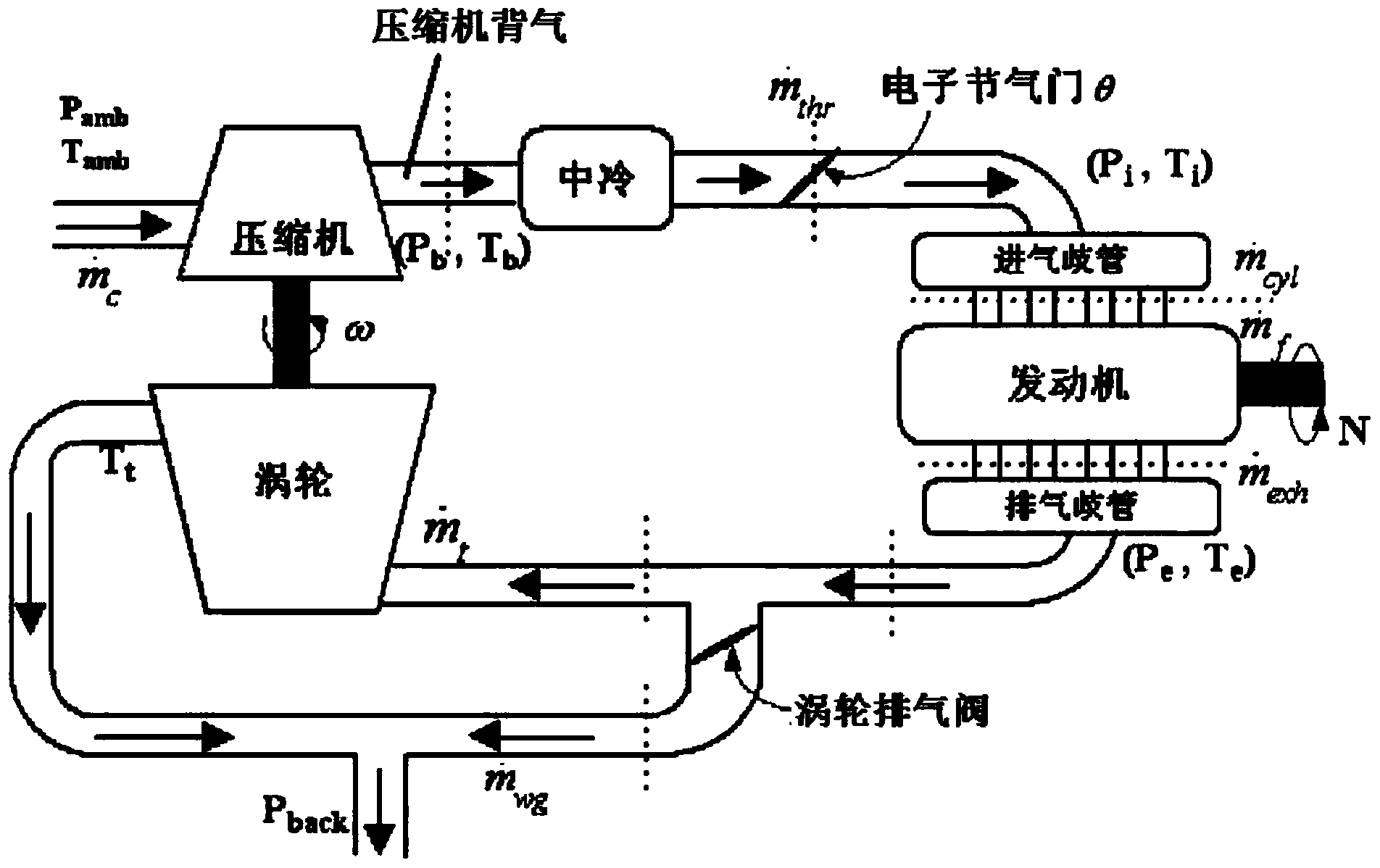
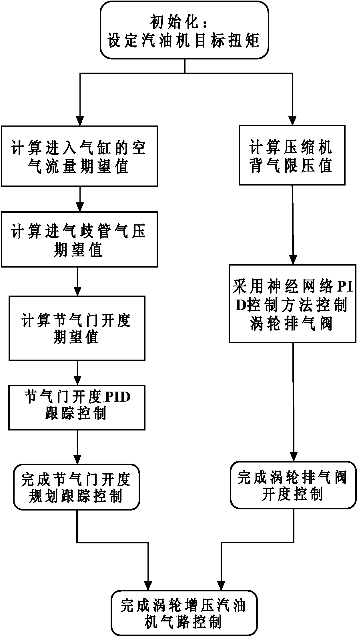
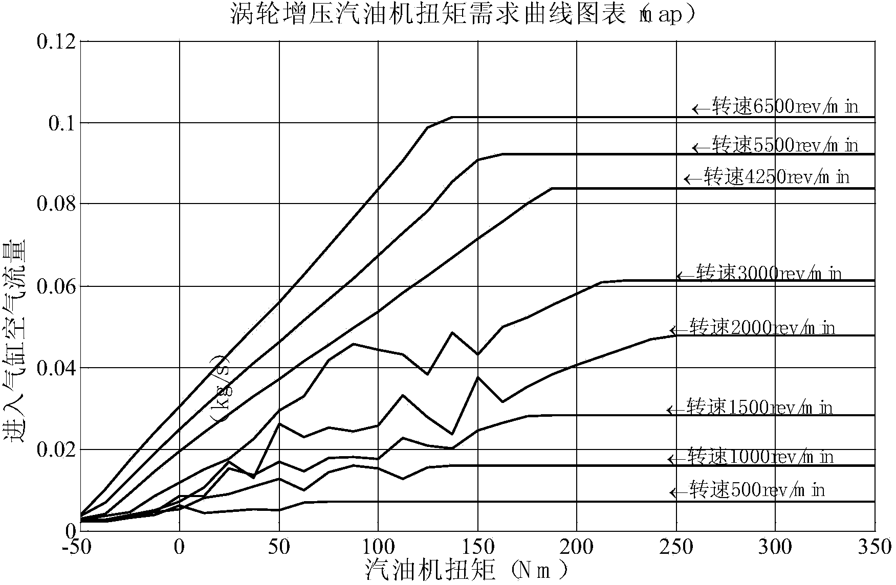
The invention discloses a method for controlling inlet air of a turbo-charging gasoline engine. The method aims at omitting excessive calibration processes in the development of an electronic control unit of the gasoline engine. The method includes the steps of (1) carrying out valve opening-degree planning tracking control: computing an expectation value of air flow entering an air cylinder of the gasoline engine with a formula in the specifications according to the torque required by a driver, computing an air pressure expectation value of an air inlet manifold according to the expectation value, obtained in the last step, of the air flow entering the air cylinder, computing an expectation valve opening-degree value through the air pressure expectation value of the air inlet manifold according to a valve flow model, and carrying out PID control to achieve electronic valve opening-degree tracking control, (2) carrying out turbine vent valve opening-degree control: computing an air-stopping ultimate pressure value of a compressor, and carrying out turbine vent valve neural network PID control.

Description

technical field [0001] The invention relates to a control method belonging to the technical field of gasoline engine electronic control, more specifically, the invention relates to a turbocharged gasoline engine air intake control method. Background technique [0002] The electronic control unit (Electronic Control Unit, referred to as ECU) of automobile gasoline engine is one of the core components that the gasoline engine can work normally. The introduction of various energy-saving and emission-reduction technologies today makes the function of the electronic control unit more powerful and the structure more and more complex, but The difficulty of development has also increased greatly, mainly including the following problems: [0003] 1. The introduction of various complex electronic control components has increased the coupling degree of various components in the control system. According to the previous calibration method, the development workload of ECU has been greatl...

Claims


Application Information

Patent Timeline
Patent Type & Authority Applications(China)
IPC IPC(8): F02D23/00F02B37/12
CPCY02T10/144Y02T10/12
Inventor 胡云峰陈虹任秉韬宫洵
Owner JILIN UNIV
Learn More