Heat exchange device for recycling flue gas waste heat

A heat exchange device and flue gas waste heat technology, which is applied in indirect heat exchangers, lighting and heating equipment, etc., can solve the problems such as the inability to popularize the waste heat recovery of flue gas, the inability to realize comprehensive utilization of waste heat, and the low heat exchange efficiency. , to achieve the effect of improving heat exchanger structure, compact structure and high heat exchange efficiency

Inactive Publication Date: 2015-06-17
三亚哈尔滨工程大学南海创新发展基地
View PDF7 Cites 1 Cited by
  • Summary
  • Abstract
  • Description
  • Claims
  • Application Information

AI Technical Summary

Problems solved by technology

[0002] At present, domestic industrial production generally uses fuel oil and coal combustion to obtain a large amount of heat required for production. During the production process, many energy-consuming equipment produce a large amount of smoke and discharge it into the atmosphere. Smoke has become the main way for general energy-consuming equipment to waste energy, such as Boiler smoke loss accounts for about 80% of boiler heat loss, while other equipment such as printing and dyeing industry setting machines, dryers, and metallurgical furnaces for metal smelting mainly consume energy through flue gas emissions, which pollute the environment and waste a lot of heat energy
Existing flue gas waste heat recovery devices mainly include air preheaters, heat pipe heat exchangers, and energy-saving ceramic heat exchangers, etc. These heat exchangers generally can only heat one type of working fluid, and the heat exchange efficiency is low, so the comprehensive utilization of waste heat cannot be realized. , and there are problems such as complex structure, easy dust accumulation, high cost, etc., so that the waste heat recovery of flue gas cannot be well promoted in industrial production

Method used


Image

  • Heat exchange device for recycling flue gas waste heat
  • Heat exchange device for recycling flue gas waste heat
  • Heat exchange device for recycling flue gas waste heat

Examples


Embodiment Construction

[0016] The present invention is described in more detail below in conjunction with accompanying drawing example:

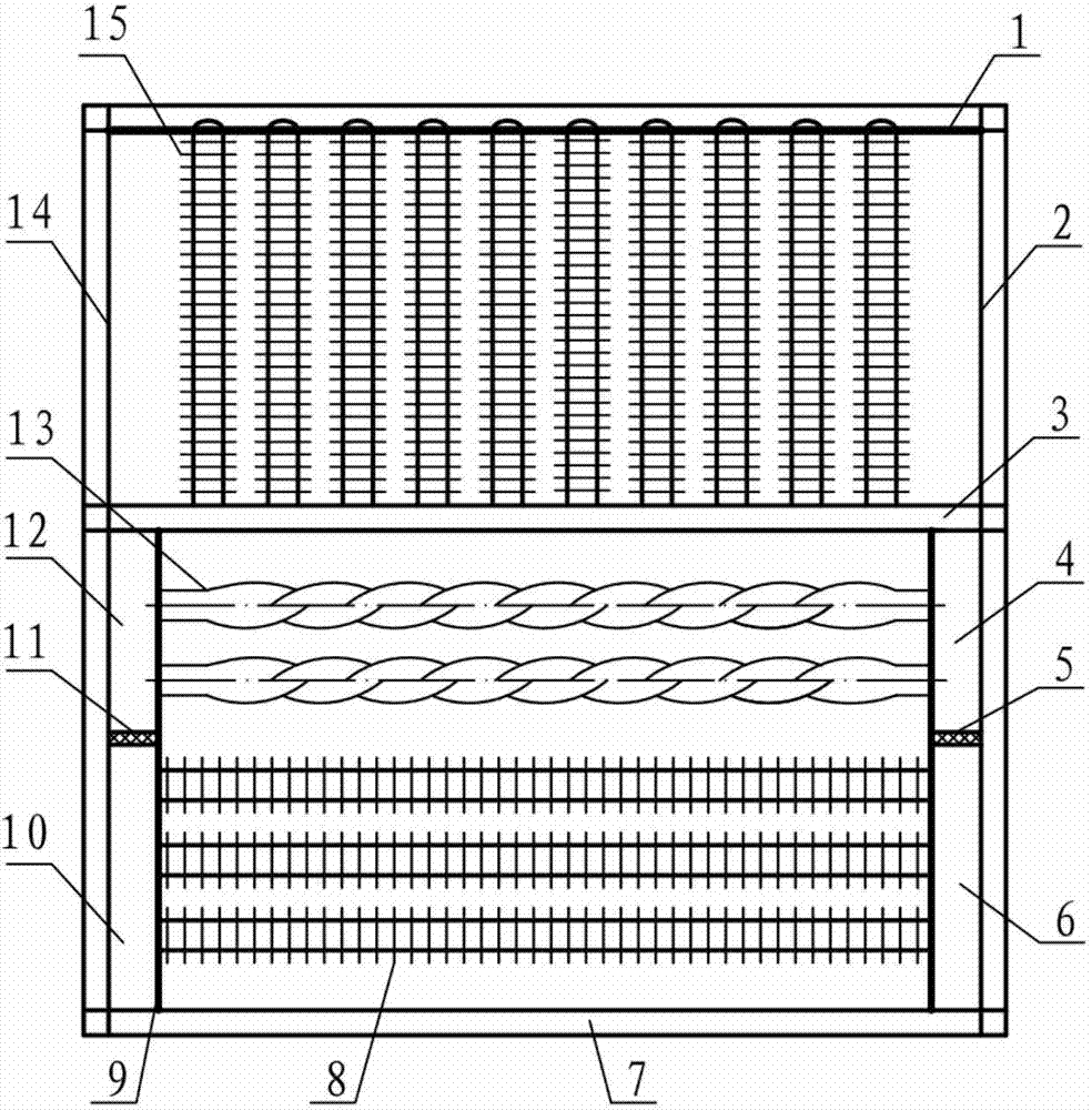
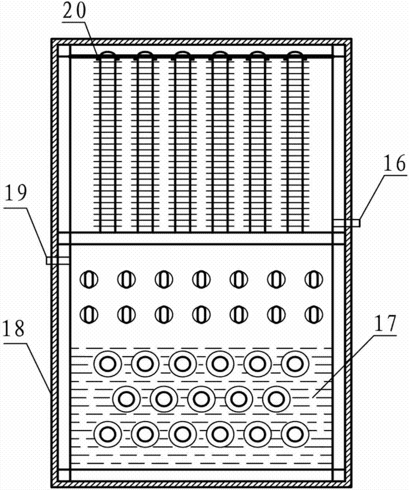
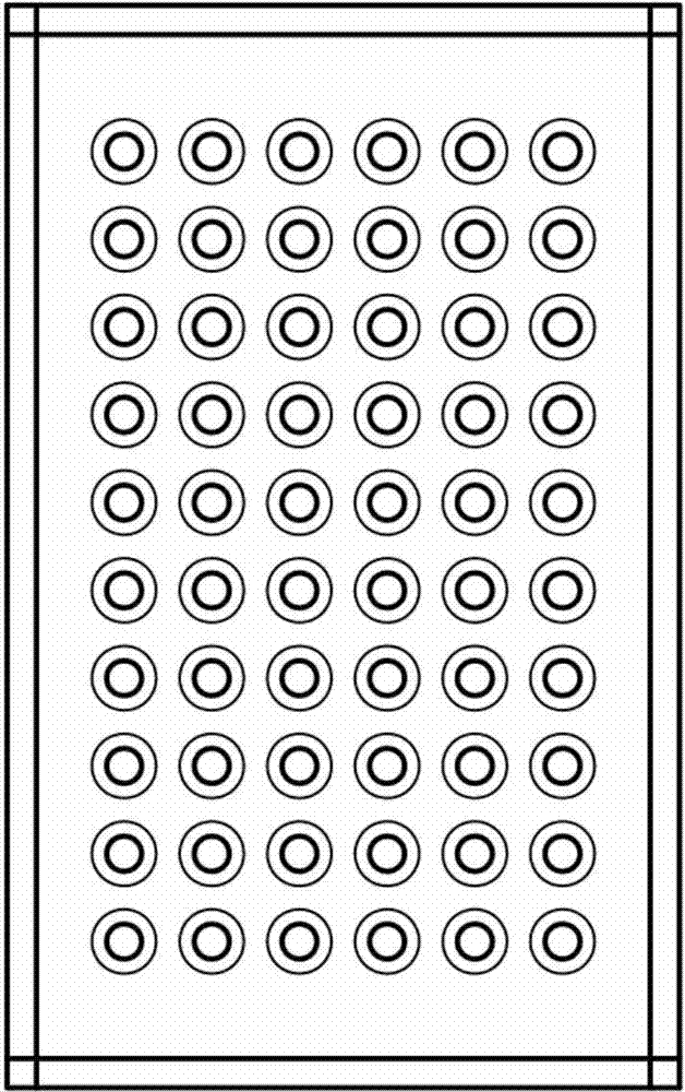
[0017] combine Figure 1~4 , a heat exchange device for recovering and utilizing flue gas waste heat in the present invention includes: a heat exchange housing 7, a sealing partition 3, a layered partition, a heat exchange pipe fitting and a fixing device, wherein the two ends of the heat exchange housing 7 correspond to Cold air inlet 14, hot water outlet 12, high-temperature flue gas inlet 10, hot air outlet 2, cold water inlet 4, and high-temperature flue gas outlet 6, the sealing partition 3 in the heat exchange shell 7 divides the heat exchange shell 7 into In the upper cavity and the lower cavity, the layered partition I11 is arranged between the hot water outlet 12 and the high-temperature flue gas inlet 10, and the layered partition II5 is arranged between the cold water inlet 4 and the high-temperature flue gas outlet 6, and in the lower chamber Multiple...


PUM


Abstract

The invention aims to provide a heat exchange device for recycling flue gas waste heat. The heat exchange device comprises a heat exchange shell, a sealed baffle, layered baffles, a heat exchange pipe fitting and a fixing device, wherein the two ends of heat exchange shell are correspondingly provided with a cold air inlet, a hot water outlet, a high-temperature flue gas inlet, a hot air outlet, a cold water inlet and a high-temperature flue gas outlet, and the heat exchange shell is divided into an upper cavity and a lower cavity by the sealed baffle in the heat exchange shell; the layered baffle I is arranged between the hot water outlet and the high-temperature flue gas inlet, the layered baffle II is arranged between the cold water inlet and the high-temperature flue gas outlet, and a plurality of rows of heat exchange pipes are deployed in the lower cavity; the heat exchange pipes are arranged on the fixed pipe plates in a two end arrangement way and are vertical to the fixed pipe plates, and a refrigerant is deployed in the lower cavity. According to the heat exchange device, the heat exchange area can be increased, the heat exchange efficiency is high, the structure of a heat exchanger can be improved, and the classified utilization of the heat energy can be realized; and two working mediums can be synchronously heated by the waste heat of the high-temperature flue gas, so that the cost can be reduced, and the promotion of the quality of energy can be realized.

Description

technical field [0001] The invention relates to an energy-saving device, in particular to a waste heat heat exchange device. Background technique [0002] At present, domestic industrial production generally uses fuel oil and coal combustion to obtain a large amount of heat required for production. During the production process, many energy-consuming equipment produce a large amount of smoke and discharge it into the atmosphere. Smoke has become the main way for general energy-consuming equipment to waste energy, such as Boiler smoke loss accounts for about 80% of boiler heat loss, while other equipment such as printing and dyeing industry setting machines, dryers, and metallurgical furnaces for metal smelting mainly consume energy through flue gas emissions, which pollute the environment and A lot of thermal energy is wasted. Existing flue gas waste heat recovery devices mainly include air preheaters, heat pipe heat exchangers, and energy-saving ceramic heat exchangers, et...

Claims


Application Information

Patent Timeline
Patent Type & Authority Patents(China)
IPC IPC(8): F28D15/02
Inventor 李彦军姜洋吴浩宇李晓明
Owner 三亚哈尔滨工程大学南海创新发展基地
Why Eureka
Try Eureka