Photovoltaic array irradiance measurement identification method

A photovoltaic array and identification method technology, applied in the field of photovoltaic power generation system operating condition detection, can solve the problems of complex system and high construction cost, and achieve the effect of less number of sensors, efficient operation, and rapid partial shadow detection effect

Active Publication Date: 2014-04-09
ZHEJIANG UNIV OF TECH
View PDF3 Cites 11 Cited by
  • Summary
  • Abstract
  • Description
  • Claims
  • Application Information

AI Technical Summary

Problems solved by technology

A large number of sensors means high

Method used


Image

  • Photovoltaic array irradiance measurement identification method
  • Photovoltaic array irradiance measurement identification method
  • Photovoltaic array irradiance measurement identification method

Examples


Embodiment Construction

[0029] The present invention will be further described in detail below in conjunction with the embodiments and the accompanying drawings, but the embodiments of the present invention are not limited thereto.

[0030] A photovoltaic array irradiance measurement and identification method includes the following steps:

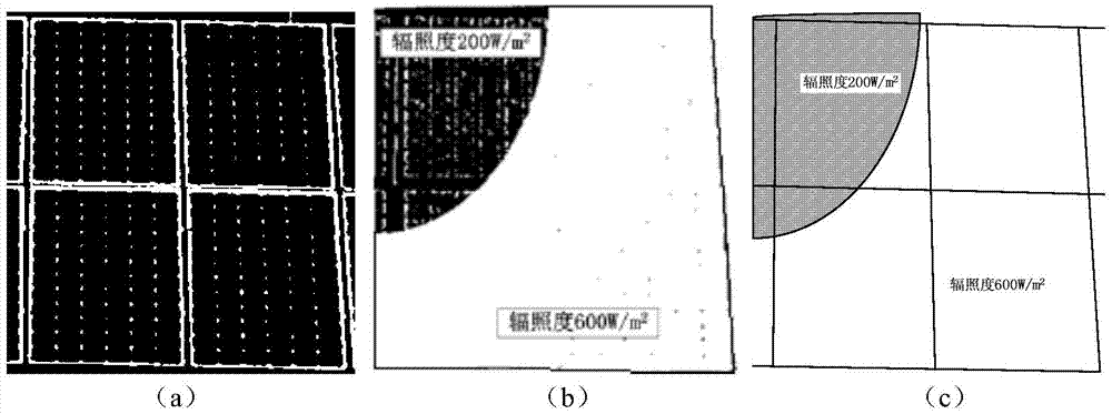
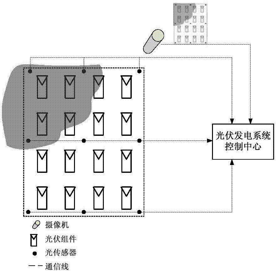
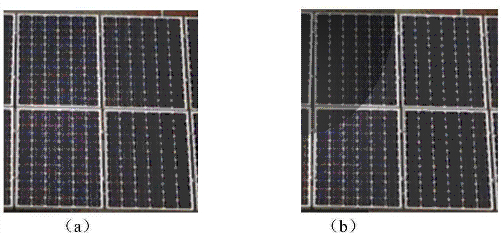
[0031] Step 1. Determine the distribution range of the photovoltaic array and the arrangement position of the photovoltaic modules in the array, and mark them. Under the premise of not affecting the working characteristics of the packaged battery, pre-treat the frame of the photovoltaic panel, such as applying paint or phosphor , making local shadows easier to identify in the captured image;

[0032] Step 2. Arrange the installation location of the light sensor and use it to measure the irradiance of the installation site. The irradiance data needs to mark the time and location of the recording moment in order to keep in sync with the collected images. The irradia...


PUM


Abstract

The invention adopts a scheme which combines image processing and sensor measurement. The method comprises the steps that light sensors are distributed in a photovoltaic array; an image acquisition device is used to shoot an image of the photovoltaic array; the image and the synchronous irradiance measurement data are transmitted to a photovoltaic power generation system control center through a communication network; the photovoltaic power generation control center analyzes and processes a photovoltaic array operation image, identifies whether a local shadow exists and the distribution scope; the irradiance data synchronously measured by the light sensors are combined; and through an interpolation and fuzzification processing technology, the irradiance of each position of the photovoltaic array is estimated. According to the invention, measurement accuracy and speed of the local shadow distribution scope and the irradiance are improved, and the arrangement number of the light sensors is greatly reduced.

Description

Technical field: [0001] The invention relates to an irradiance measurement and identification technology when a photovoltaic array encounters partial shadows in a photovoltaic power generation system, and belongs to the field of detection of operating conditions of a photovoltaic power generation system. Background technique: [0002] Solar photovoltaic power generation technology has become the main new energy power generation method after wind power generation because of its clean and pollution-free, convenient installation, and no geographical restrictions. With the reduction in the price of photovoltaic modules and the introduction of government subsidy measures, the installed capacity of photovoltaic power generation has grown rapidly, including large-capacity desert photovoltaic power plants and a large number of scattered small and medium-capacity building photovoltaic systems. [0003] The photovoltaic array in the photovoltaic power generation system is composed of ...

Claims


Application Information

Patent Timeline
IPC IPC(8): G01J1/00
Inventor 戚军张晓峰
Owner ZHEJIANG UNIV OF TECH
Why Eureka
Try Eureka