Interface of a welding power source and method for defining the same

A welding power supply and interface technology, applied in welding equipment, arc welding equipment, manufacturing tools, etc., can solve the problems of high installation cost, long waiting time, and heavy load of welding manipulators, so as to avoid long-distance travel, avoid mistakes, and avoid serious accidents. the wrong effect

Active Publication Date: 2014-04-09
FRONIUS INTERNATIONAL GMBH
View PDF7 Cites 2 Cited by
  • Summary
  • Abstract
  • Description
  • Claims
  • Application Information

AI Technical Summary

Problems solved by technology

If this expertise is mostly present, this person is also mostly heavily loaded, which leads to long waiting times when adjusting the interface
Customers do not accept such long waiting times due to the high installation costs e.g. of welding robots
Furthermore, it is troublesome that professionals often have to travel long distances to establish such interfaces on site due to globalization
This is very unpleasant especially when it is only necessary to improve a small problem with an already delivered interface

Method used


Image

  • Interface of a welding power source and method for defining the same
  • Interface of a welding power source and method for defining the same
  • Interface of a welding power source and method for defining the same

Examples


Embodiment Construction

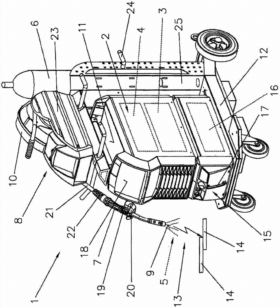
[0054] figure 1 A known welding device 1 or welding equipment is shown for different processes or methods such as MIG / MAG welding or WIG / TIG welding or electrode welding methods, twin wire / tandem welding methods, plasma or brazing methods etc. Wait.

[0055] The welding device 1 comprises a power source 2 having a power part 3 disposed therein, a control device 4 and other not-shown parts and lines, such as switching mechanisms, control valves and the like. The control device 4 is connected, for example, to a control valve which is arranged between the gas reservoir 6 and the welding torch 7 or torch in a supply line for a gas 5, in particular a shielding gas such as CO2, helium or argon, etc. between.

[0056] In addition, a wire feed 8 can also be activated via the control unit 4 , which is often used for MIG / MAG welding, wherein additional material or welding wire 9 is fed via a supply line from a storage reel 10 or wire coil to the area of ​​the welding torch 7 middle. ...


PUM


Abstract

The invention relates to a method for defining an interface (32, 42, 52, 62) of a welding power source (31, 41, 51, 61) for communication with an external machine (26) that is connected to the interface. A freely configurable interface is used in the welding device, said interface being configured and activated via software directly via the operating panel of the welding power source or an external device that can be connected to the welding power source. A parameter of the welding device is allocated to an internal and/or external connection (101...105). Optionally, a link is established by stringing together graphic symbols of the software. The invention further relates to a welding power source (31, 41, 51, 61) and to a computer program which are set up for performing or storing the process according to the invention.

Description

technical field [0001] The invention relates to a method for defining an interface of a welding power source, a welding power source with an interface and a computer with a computer program stored thereon, as stated in the preambles of claims 1, 10 and 11 program product. Background technique [0002] The increasing use of data connections or networking in the field of industrial processes means that devices used in such processes often have interfaces for output transmission or for communication with other devices. An example of such equipment is a welding power source, which is generally used to create or otherwise make a weld. Besides the own power supply, which forms the so-called "heart" of the welding power supply, the welding power supply also includes other components, which are usually used for welding. For example, the welding power source may include means for generating and controlling the welding gas flow and / or means for cooling the welding torch. [0003] T...

Claims


Application Information

Patent Timeline
Patent Type & Authority Applications(China)
IPC IPC(8): B23K9/10
CPCB23K9/1006B23K9/1087
Inventor 伯恩哈德·斯皮西奇托马斯·埃森科尔伯帕特里克·克里姆斯坦恩
Owner FRONIUS INTERNATIONAL GMBH
Why Eureka
Try Eureka