
Secondary battery

A secondary battery and battery shell technology, applied in secondary batteries, secondary battery manufacturing, batteries, etc., can solve problems such as increased plate temperature, decreased heat dissipation of the plate, and decreased battery characteristics, achieving high energy density , high reliability, effective heating effect

Inactive Publication Date: 2014-04-09
SHIN KOBE ELECTRIC MASCH CO LTD
View PDF6 Cites 4 Cited by
  • Summary
  • Abstract
  • Description
  • Claims
  • Application Information

AI Technical Summary

Problems solved by technology

Therefore, the distance from the surface of the battery case to the center of the battery case increases, the heat dissipation of the pole plate in the center of the battery case decreases, and the temperature rise of the pole plate increases.
As a result, there is a risk of deterioration in battery characteristics, reliability, and safety.

Method used


Image

  • Secondary battery
  • Secondary battery
  • Secondary battery

Examples


Embodiment 1

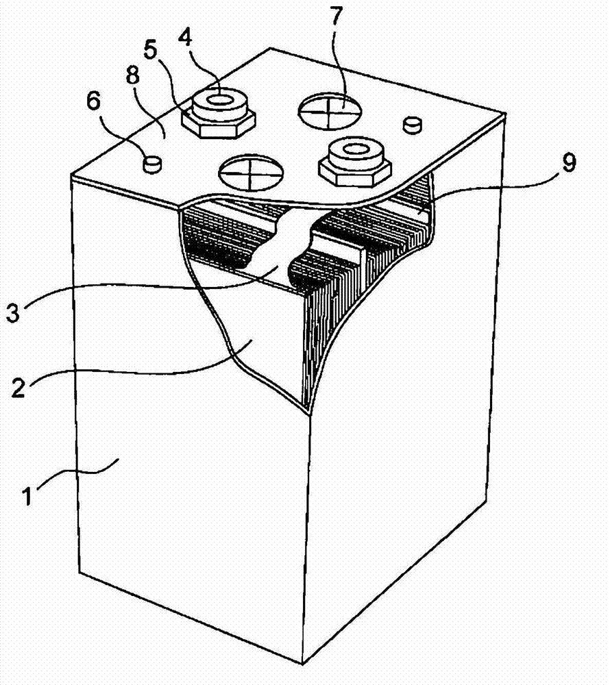
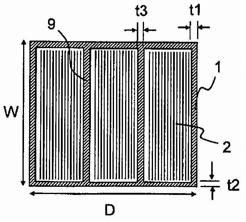
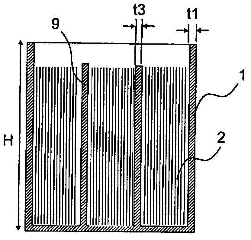
[0038] figure 1 is a partially cutaway perspective view showing a secondary battery according to an embodiment of the present invention, figure 2 yes figure 1 A schematic top sectional view of the secondary battery, image 3 yesfigure 1 A schematic side cross-sectional view of a secondary battery. exist figure 2 and image 3 In , the arrangement of the laminated body 2 and the battery case 1 of the present invention is shown, and tabs, covers, and current-carrying members of the laminated body are omitted. The illustration shows a stacked lithium-ion secondary battery with a battery capacity of 210Ah. The laminated body 2 is accommodated in the battery case 1 , and the laminated body 2 is electrically connected to the external terminal 4 via the tab 3 . The external terminal 4 is fixed to the cover plate 8 by fastening members 5 such as nuts. In addition, an injection hole plug 6 for closing the injection hole for injecting the electrolyte solution and a safety valve ...

Embodiment 2

[0046] Figure 4 It is a schematic plan cross-sectional view showing a secondary battery according to an embodiment of the present invention. Figure 5 yes Figure 4 A schematic side sectional view of the . This secondary battery is a 280 Ah laminated lithium ion secondary battery in which the laminated body 2 is composed of four sets. The capacity of one set of laminated bodies 2 is 70 Ah. The external dimensions of the battery case 1 are: the width W is 130 mm, the depth D is 205 mm, and the height H is 220 mm. The battery case 1 is composed of an outer peripheral body 11 made of stainless steel and a plurality of partition plates 9 . The partition plate 9 is fixed to the outer peripheral body 11 by welding. Such as Figure 5 As shown, compared with the outer peripheral body 11 of the battery case 1, the height of the partition plate 9 is lowered, and the bottom surface 11a of the outer peripheral body 11 of the battery case 1 is not in contact with the partition plate...


PUM


Abstract

The present invention is a secondary battery in which a laminate is sealed in a battery can that has a floor, the laminate having the following positioned in an alternating manner in strips: a metallic current collector having a negative electrode active material layer formed on the surface thereof, a separator for holding electrolyte, and another metallic current collector having a positive electrode active material layer formed on the surface thereof. This secondary battery also contains at least one partition that divides the interior space of the battery can and faces the wide surface of the laminate between laminates of the plurality of laminates stored in the battery can.

Description

technical field [0001] The present invention relates to a configuration of a secondary battery. Background technique [0002] In recent years, against the backdrop of environmental issues, secondary batteries represented by lithium-ion batteries have been used not only in hybrid electric vehicles (HEV), electric vehicles (EV), forklifts, bulldozers, etc., but also in UPS (Uninterruptible power supply device), solar power storage and other industrial applications are also used. With the expansion of applications of such secondary batteries, larger capacity and higher energy density are required. [0003] In addition, in addition to these enhancements in performance, enhancement of safety has also become an important issue. As the secondary battery, there are nickel-cadmium batteries, nickel-hydrogen batteries, lithium-ion batteries, and the like. Due to the toxicity of cadmium and other reasons, nickel-cadmium batteries are being converted to nickel-metal hydride batteries...

Claims


Application Information

Patent Timeline
Patent Type & Authority Applications(China)
IPC IPC(8): H01M10/04H01M2/02H01M10/0585H01M50/10H01M50/112H01M50/14
CPCH01M2/024H01M2/0242H01M10/0525Y02E60/12H01M10/0436Y02T10/7011H01M2/1077Y02E60/122H01M10/0585H01M50/112H01M50/10H01M50/14Y02E60/10Y02P70/50H01M2220/20Y02T10/70
Inventor 田中明
Owner SHIN KOBE ELECTRIC MASCH CO LTD
Learn More