
Depositing apparatus and method for manufacturing organic light emitting diode display using the same

A technology of deposition device and manufacturing method, applied in lighting device, electroluminescence light source, semiconductor/solid-state device manufacturing, etc., can solve problems such as penetration of organic substances, achieve high resolution and suppress shadow phenomenon

Active Publication Date: 2014-04-16
SAMSUNG DISPLAY CO LTD
View PDF3 Cites 7 Cited by
  • Summary
  • Abstract
  • Description
  • Claims
  • Application Information

AI Technical Summary

Problems solved by technology

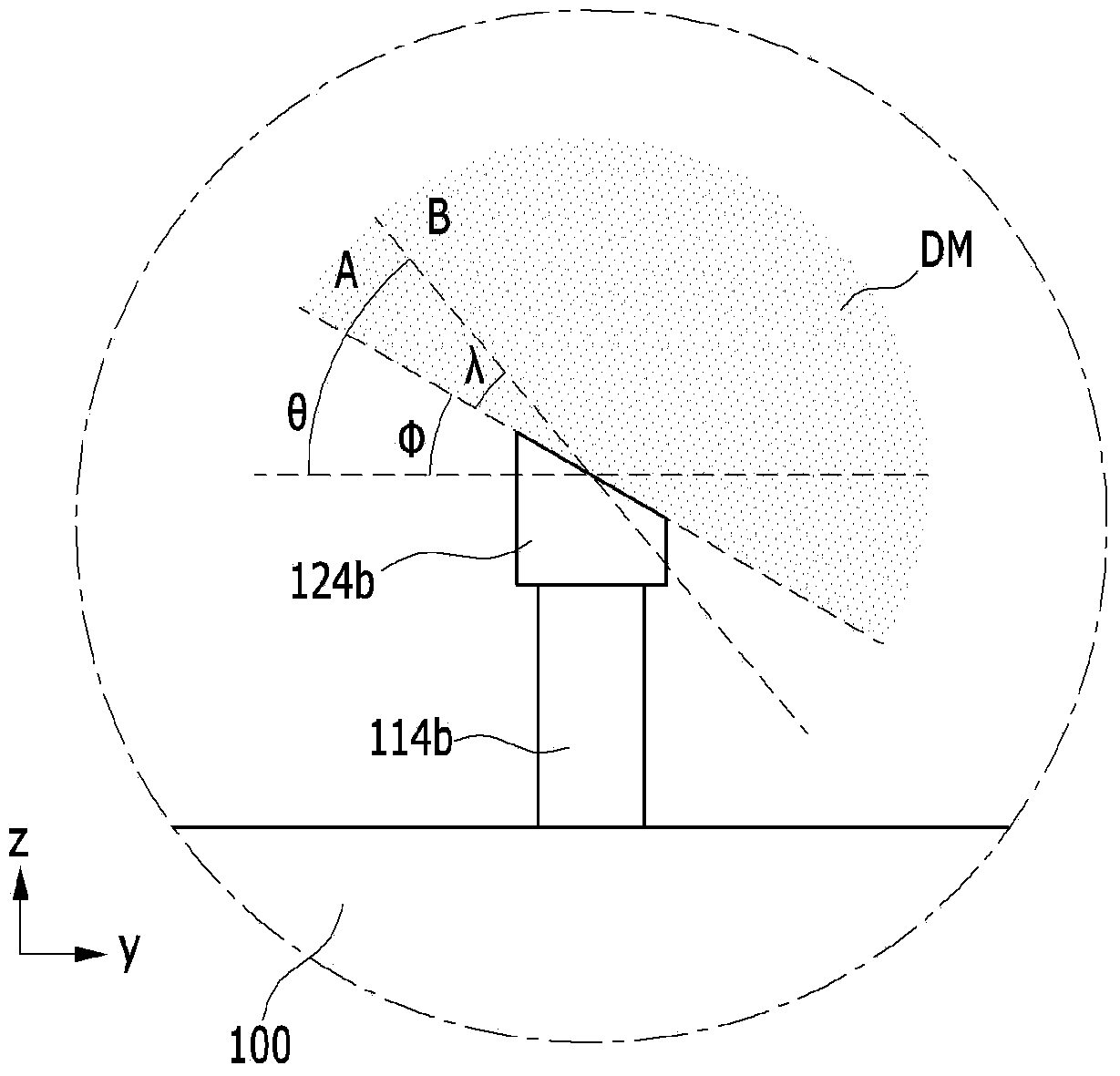
[0005] However, depending on the angle at which the deposition material is sprayed and reaches the substrate, a shadow phenomenon occurs in which the organic material penetrates between the deposition mask and the substrate

Method used


Image

  • Depositing apparatus and method for manufacturing organic light emitting diode display using the same
  • Depositing apparatus and method for manufacturing organic light emitting diode display using the same
  • Depositing apparatus and method for manufacturing organic light emitting diode display using the same

Examples


Embodiment Construction

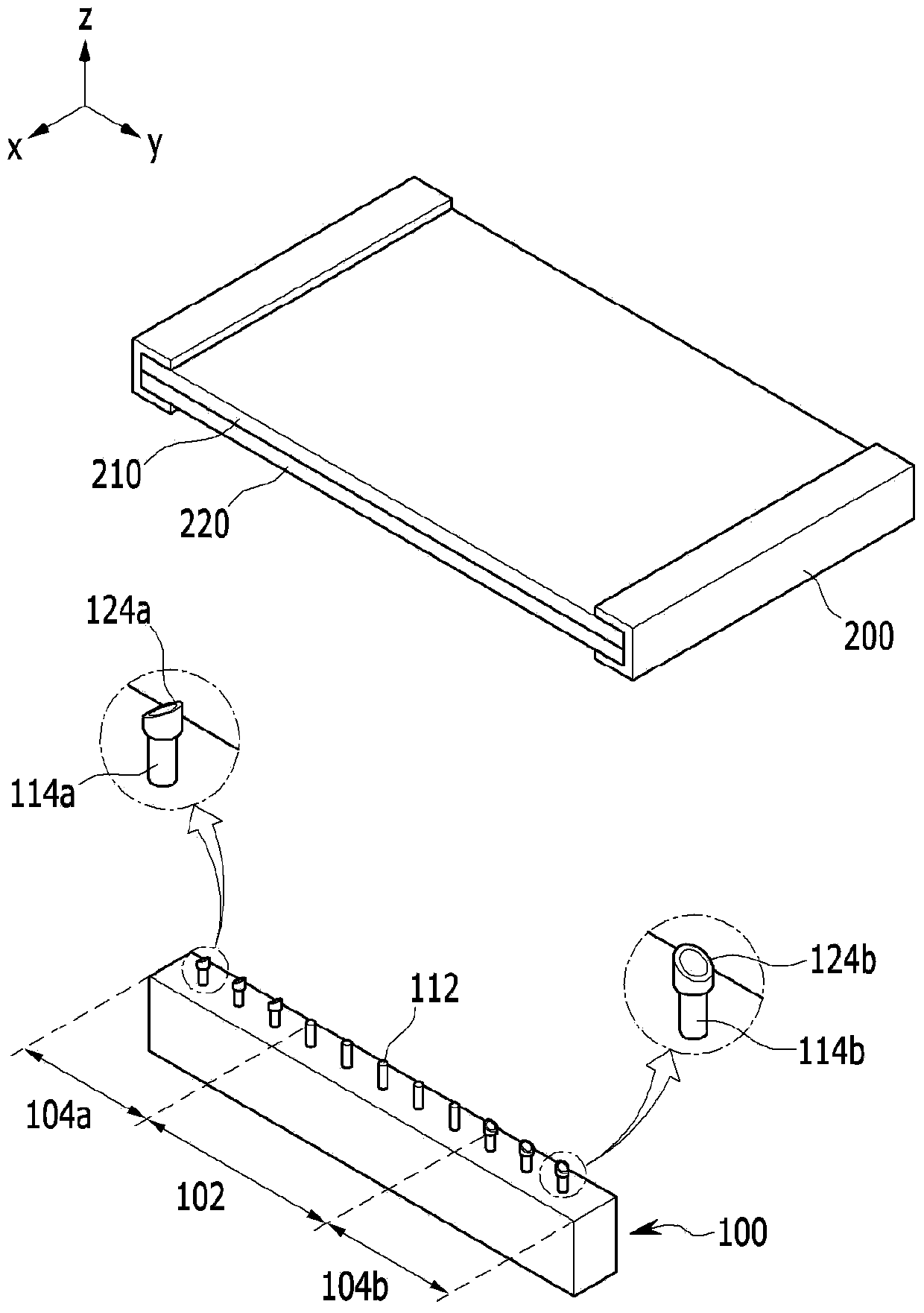
[0030] Hereinafter, a deposition apparatus according to the present invention and a method of manufacturing an organic light emitting display device using the deposition apparatus will be described in detail with reference to the accompanying drawings. However, the present invention is not limited to the embodiments disclosed below, and can be implemented in other various forms. These embodiments are only intended to fully disclose the present invention and to fully inform those skilled in the art of the scope of the invention. supply. In the drawings, the same reference numerals designate the same elements.

[0031] In addition, throughout the entire specification, when it is stated that a certain part "includes" a certain constituent element, unless otherwise specifically mentioned, it will mean that other constituent elements may also be included rather than excluded. In addition, throughout the entire specification, when it is expressed as "on", it means that it is locate...


PUM


Abstract

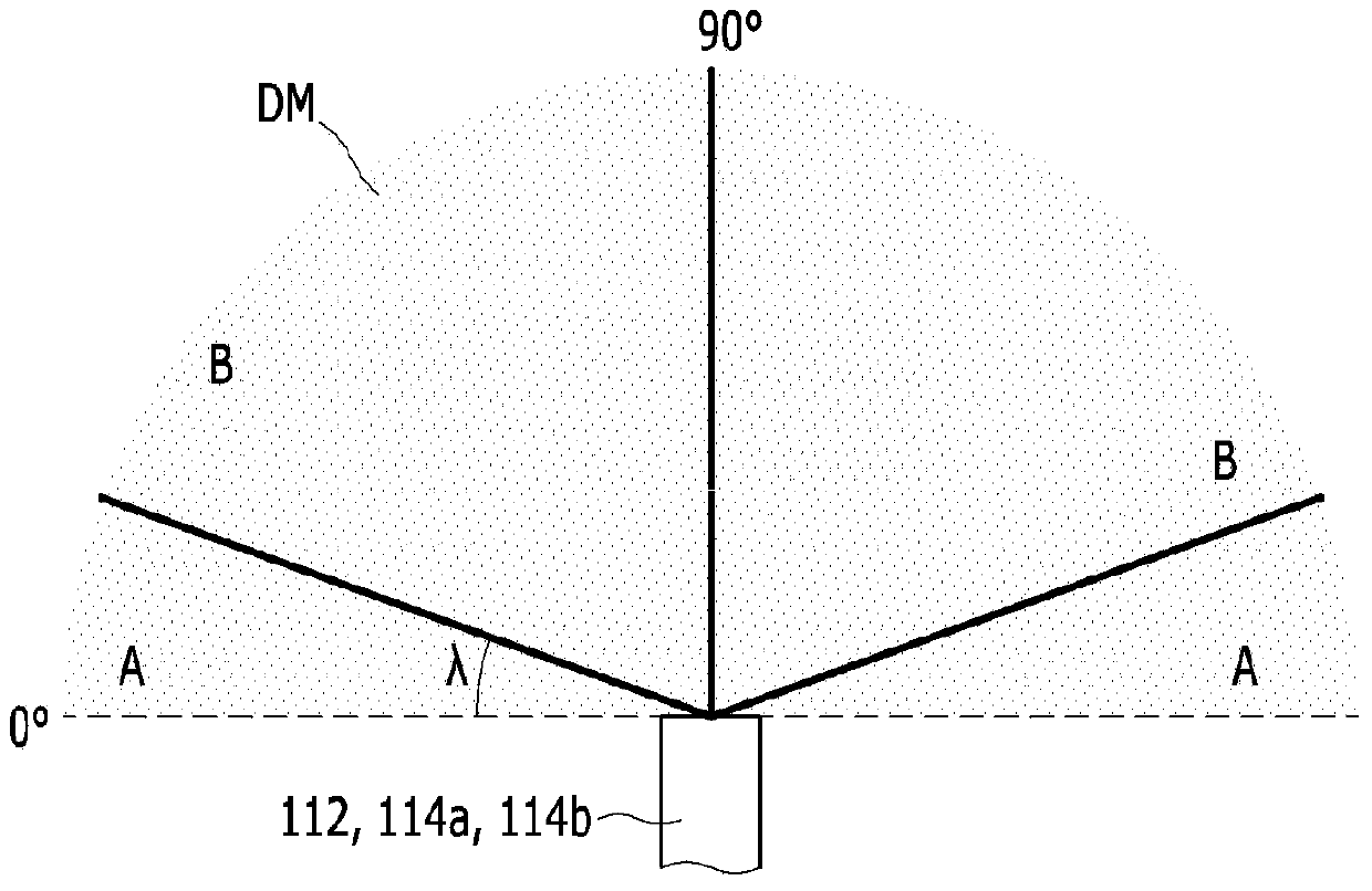
The depositing apparatus of the invention comprises a depositing source used for accepting deposited substances; and a plurality of nozzles arranged on one side of the depositing source in a first direction and used for ejecting the deposited substances to opposite substrates. The depositing source is divided into a central area and peripheral areas at two ends of the central area with the first direction as a standard. The depositing apparatus also comprises nozzle tops arranged on the nozzles of each peripheral area in a detachable mode, allowing the tail end surfaces ejecting the deposited substances to form inclined angles with the surface of the substrates in the first direction and facing the outer side direction of the depositing source. According to the embodiment of the invention, by increasing the incidence angles of the deposited substances to the substrates, the shadow permeated by the deposited substances between deposition masks and substrates can be restrained, deposition remains can be reduced and deposition uniformity and efficiency can be raised, and thereby the high resolution of an organic light emitting display can be easily realized.

Description

technical field [0001] The present invention relates to a deposition device and a method for manufacturing an organic light-emitting display device using the same, in particular to a deposition device capable of preventing shadowing by controlling the angle at which a deposition material is sprayed, and a method for manufacturing an organic light-emitting display device. Background technique [0002] Among display devices, organic light-emitting display devices not only have the advantages of wide viewing angle and excellent contrast ratio, but also have advantages such as fast response speed, and thus are attracting attention as next-generation display devices. [0003] Generally, in order to realize colors by recombining holes and electrons injected from the anode and cathode in the light emitting layer to emit light, the organic light emitting display device has a stacked structure in which the light emitting layer is inserted between the anode and the cathode. However, i...

Claims


Application Information

Patent Timeline
Patent Type & Authority Applications(China)
IPC IPC(8): C23C16/455H01L51/56
CPCH05B33/10H10K71/00H10K71/164H10K71/166
Inventor 白大源
Owner SAMSUNG DISPLAY CO LTD
Learn More