Resistance strain gauge

A resistance strain gauge and sensitive grid technology, applied in the direction of electric/magnetic solid deformation measurement, electromagnetic measurement device, etc., can solve the problems of large dispersion of sensitivity coefficient, small peripheral surface area of ​​grid wire, poor accuracy, etc., to achieve good heat dissipation, The effect of small dispersion of sensitivity coefficient and accurate size

Inactive Publication Date: 2014-04-16
GUANGXI UNIVERSITY OF TECHNOLOGY
View PDF5 Cites 15 Cited by
  • Summary
  • Abstract
  • Description
  • Claims
  • Application Information

AI Technical Summary

Problems solved by technology

However, the existing resistance strain gauges have the following disadvantages: (1) The sensitivity coefficient is highly disp

Method used


Image

  • Resistance strain gauge

Examples


Embodiment Construction

[0013] The preferred embodiments of the present invention will be described below in conjunction with the accompanying drawings. It should be understood that the preferred embodiments described here are only used to illustrate and explain the present invention, and are not intended to limit the present invention.

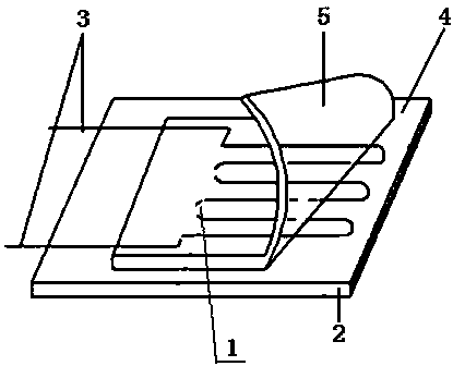
[0014] Such as figure 1 As shown, a strain gauge of the present invention includes a base 2, the upper panel of the base 2 is pasted with a sensitive grid 1 through an adhesive 4, and the left and right ends of the sensitive grid 1 are respectively connected with lead wires 3. The cross-section of the sensitive grid 1 is set as a rectangle, and a surface covering 5 is set on the sensitive grid 1 .

[0015] Further, the sensitive gate 1 is made of semiconductor material.

[0016] Further, the sensitive grid 1 is a foil sheet.

[0017] In the resistance strain gauge of the present invention, the section of the sensitive grid is rectangular, so the surrounding surfac...


PUM


Abstract

The invention discloses a resistance strain gauge which comprises a substrate. A sensitive grid is stuck to an upper panel of the substrate through a binder. The left end and the right end of the sensitive grid are connected with leads respectively, and the section of the sensitive grid is arranged to be rectangular. A surface covering is arranged on the sensitive grid which is made of semiconductor materials. The sensitive grid is a foil type piece. The resistance strain gauge is small in sensitivity coefficient dispersibility and high in measurement accuracy.

Description

technical field [0001] The invention relates to a resistance strain gauge. Background technique [0002] Resistance strain gauges, also known as resistance strain gauges, referred to as strain gauges or strain gauges, are components for measuring strain composed of sensitive grids and the like. It converts changes in strain on mechanical components into changes in electrical resistance. The existing resistance strain gauge is made of Φ=0.02-0.05mm constantan wire or nickel-chromium wire wound into a grid shape (or corroded into a grid shape with a very thin metal foil) and sandwiched between two layers of insulating sheets (base). become. Use silver-plated copper wires to connect to the wire grid of the strain gauge as the lead wire of the resistance gauge. The resistance strain gauge is used as a sensing element, and it is firmly pasted on the measuring point of the component. After the component is stressed, due to the strain of the measuring point, the strain gauge is ...

Claims


Application Information

Patent Timeline
IPC IPC(8): G01B7/16
Inventor 韦文斌琚裕强
Owner GUANGXI UNIVERSITY OF TECHNOLOGY
Why Eureka
Try Eureka