A Surface Plasmon Resonance Coupling Optical Element

A surface plasmon and optical element technology, applied in the field of ion resonance coupling optical elements, can solve the problem of affecting imaging quality and analysis effect, displacement of excitation spot position, difficult to ideally match the refractive index of prism, bonding oil and substrate, etc. problems, to save the trouble of angle correction and bonding oil operation, improve detection sensitivity, and avoid changes in light distribution.

Active Publication Date: 2016-01-20
INST OF CHEM CHINESE ACAD OF SCI
View PDF4 Cites 0 Cited by
  • Summary
  • Abstract
  • Description
  • Claims
  • Application Information

AI Technical Summary

Problems solved by technology

[0005] 1. The shape of the prism is fixed, the excitation light cannot always be perpendicular to the incident surface of the prism, and the reflected light cannot always be perpendicular to the exit surface of the prism. When the light excitation angle changes, the position of the excitation spot will shift due to the light refraction effect , causing the light distribution to change, thus affecting the analysis effect; and it will also bring about the correction of the light excitation angle
[0006] 2. In order to reduce cost and facilitate use, the sensing film is mostly prepared on the substrate, and then pasted on the bottom surface of the prism with adhesive oil. The operation of adhesive oil is easy to generate air bubbles, which affects the imaging quality and analysis effect
[0007] 3. The incident surface of the excitation light and the prism, the reflected light and the exit surface of the prism cannot always be kept vertical, and the refractive index of the prism, adhesive oil and substrate is difficult to match ideally, which will bring reflection interference problems at multiple interfaces
[0008] All the above problems, in addition to the trouble of angle correction, will seriously affect the analysis quality of surface plasmon resonance and surface plasmon resonance imaging system

Method used


Image

  • A Surface Plasmon Resonance Coupling Optical Element
  • A Surface Plasmon Resonance Coupling Optical Element
  • A Surface Plasmon Resonance Coupling Optical Element

Examples


Embodiment Construction

[0035] The specific implementation manners of the present invention will be described in detail below in conjunction with the accompanying drawings and typical embodiments. However, those skilled in the art understand that the following examples are used to illustrate the present invention, but not to limit the scope of the present invention. Those skilled in the art can make modifications and equivalent transformations according to the description, claims and drawings of the present invention, and such modifications and transformations should not be excluded from the scope of the present invention. Any improvements and changes made on the basis of the present invention are within the protection scope of the present invention.

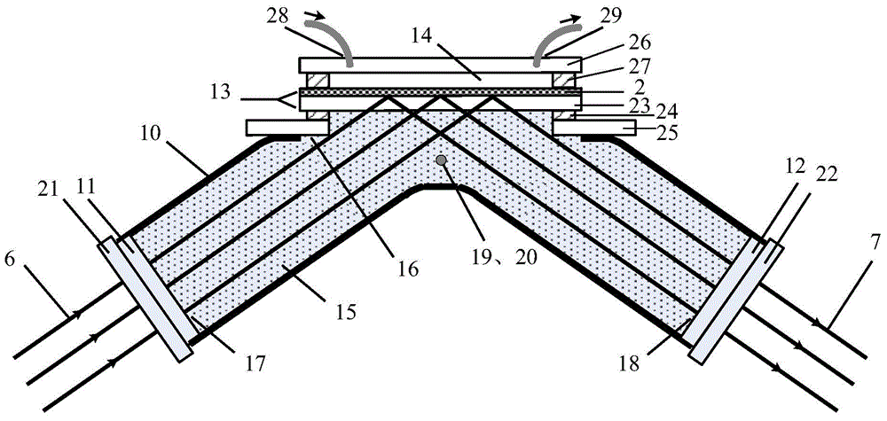
[0036] The structure diagram of the present invention is as figure 2 shown. The surface plasmon resonance coupling optical element includes a soft cavity 10 , two optical windows 11 , 12 , a sensor chip 13 , a sample flow cell 14 , and an optically ...


PUM

PropertyMeasurementUnit
thicknessaaaaaaaaaa
thicknessaaaaaaaaaa

Abstract

The invention relates to a surface plasma resonance coupling optical element. The optical element comprises a soft cavity, two optical windows, a sensing chip and a sample flowing cell, wherein the two optical windows are respectively installed at two opposite openings of the soft cavity in a sealing manner and are respectively used as an exciting light incident optical window and a reflected light emergent optical window of the surface plasma resonance coupling optical element, the sensing chip is installed at the center opening of the soft cavity in the sealing manner so as to form a sealing hollow cavity; the optical element also comprises optical transparent liquid filling the sealing hollow cavity, and the sample flowing cell is arranged on the sensing chip. The optical element has the advantages of keeping the exciting light to be always vertical to the incident optical window and keeping the reflected light to be always vertical to the emergent optical window, not needing to correct the angle, not using binding oil for fixing the sensing chip, and reducing interference of reflect of multiple interfaces, can be widely used by surface plasma resonance systems and surface plasma resonance imaging systems.

Description

technical field [0001] The invention relates to a surface plasmon resonance and imaging analyzer, in particular to a surface plasmon resonance coupling optical element. Background technique [0002] Surface plasmon resonance is a label-free, in situ and real-time interface analysis technique. The occurrence condition of surface plasmon resonance changes with the change of the refractive index of the sample on the sensing film-medium interface. Therefore, through surface plasmon resonance analysis, the refractive index and thickness information of the sample on the surface of the sensing film can be obtained, and the physical and chemical reactions on the surface of the sensing film can be monitored and analyzed. If the target molecule is bonded to the surface of the sensing film, Specific molecular interaction analysis can then be performed. Based on surface plasmon resonance technology, two types of analysis systems, surface plasmon resonance and surface plasmon resonance...

Claims


Application Information

Patent Timeline
Patent Type & Authority Patents(China)
IPC IPC(8): G01N21/552
Inventor 许吉英陈义
Owner INST OF CHEM CHINESE ACAD OF SCI
Why Eureka
Try Eureka