
System and method for debugging frequency converter

A technology for debugging systems and frequency converters, applied in the field of frequency converters, can solve problems such as incomprehensible logical structures, low operability, and low efficiency, and achieve the effect of avoiding low operating efficiency and improving the ease of operation

Active Publication Date: 2014-04-16
SHENZHEN HOPEWIND ELECTRIC CO LTD
View PDF5 Cites 20 Cited by
  • Summary
  • Abstract
  • Description
  • Claims
  • Application Information

AI Technical Summary

Problems solved by technology

The existing inverter debugging software usually has the following two types, one is the inverter debugging software provided by foreign companies, Hong Kong and Taiwan companies, such as the VFD inverter debugging software provided by Delta, which usually has many application functions, but the operation interface It is more complicated, and the logical structure is difficult to understand, and during data transmission, the operator needs to manually input the hexadecimal communication data; during parameter management, the operator needs to manually input the hexadecimal address and length. For operators, its operability is low and cannot meet the actual needs in real applications; the other is the inverter debugging software usually produced by domestic manufacturers, its operation interface is usually simple and intuitive, but its application functions are not Relatively limited, for example, during data transmission, only one bit can be read and written for each parameter, and its efficiency is not much different from that based on the keyboard input of the inverter, and there is a problem of low efficiency

Method used


Image

  • System and method for debugging frequency converter
  • System and method for debugging frequency converter
  • System and method for debugging frequency converter

Examples


Embodiment Construction

[0049] The technical scheme of the present invention will be described in further detail below in conjunction with the accompanying drawings and specific examples, so that those skilled in the art can better understand the present invention and implement it, but the examples given are not intended to limit the present invention .

[0050] The technical problem to be solved by the present invention is to provide a simple and convenient tool that is suitable for operators of various professional technical levels in view of the problems of existing debugging tools such as the complexity of use, the complexity of content, and the high requirements of operation. Frequency converter debugging system, method and software.

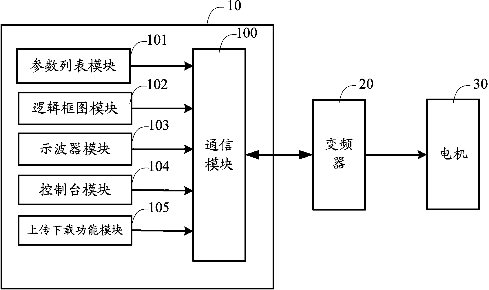
[0051] Such as figure 1 As shown, a frequency converter debugging system provided by an embodiment of the present invention includes:

[0052] The frequency converter 20 is used to provide a control signal to the target motor 30;

[0053] The upper computer 10 ...


PUM


Abstract

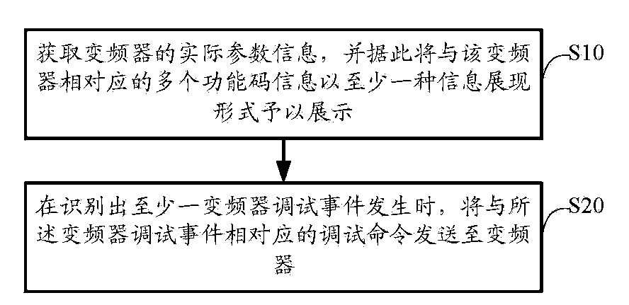
The invention discloses a system and method for debugging a frequency converter. The method comprises the steps of obtaining actual parameter information of the frequency converter, and displaying a plurality of pieces of function code information corresponding to the frequency converter in a mode of displaying at least one kind of information according to the actual parameter information; and sending debugging commands corresponding to frequency converter debugging events to the frequency converter when recognizing that at least one frequency converter debugging event occurs. Product model information, version information and machine model information of the frequency converter serve as the basis, function code parameter lists matched with the frequency converter are automatically selected, operators can visually operate different frequency converters by selecting the corresponding parameter lists when performing operation, and software operation convenience is improved.

Description

technical field [0001] The present invention relates to the technical field of frequency converters, in particular to a frequency converter debugging system and method. Background technique [0002] Inverter (Variable-frequency Drive, VFD) is a power control device that uses frequency conversion technology and microelectronics technology to achieve the purpose of controlling the motor by changing the frequency of the motor's operating power supply. Knownly, the frequency converter is mainly composed of a rectification (AC to DC) unit, a filter unit, an inverter (DC to AC) unit, a braking unit, a drive unit, a detection unit, and a micro-processing unit. The inverter adjusts the voltage and frequency of the output power supply by turning on / off the internal IGBT (Insulated Gate Bipolar Transistor), and provides the required power supply voltage according to the actual needs of the motor, thereby achieving energy saving, regulation In addition, in practical applications, the ...

Claims


Application Information

Patent Timeline
Patent Type & Authority Applications(China)
IPC IPC(8): G01R31/00
Inventor 朱慧徐中领
Owner SHENZHEN HOPEWIND ELECTRIC CO LTD
Learn More