PTC liquid heater

A liquid heater, heater technology, applied in fluid heaters, water heaters, ohmic resistance heating and other directions, can solve the problems of unreliable limitation, low heating efficiency, affecting heating effect, etc., to ensure property and personal safety, The effect of saving power consumption and improving heating efficiency

Active Publication Date: 2014-04-23
嘉善县魏塘资产管理有限公司
View PDF7 Cites 7 Cited by
  • Summary
  • Abstract
  • Description
  • Claims
  • Application Information

AI Technical Summary

Problems solved by technology

[0003] Although the above two patent schemes each have the technical effect of the technical effect column of the specification (see paragraph 10 of the specification of CN201476268U and paragraph 8 of the specification of CN201937849U), there are the following disadvantages: First, due to the fact that it is formed in the length direction of the heater body The wall of the central liquid heating chamber is smooth, so on the one hand, it will affect the heating effect of the liquid flowing through the liquid heating chamber, on the other hand, the low heating efficiency is not enough to save power consumption, and on the other hand, it will cause production heating. Second, it is unsafe, because when the liquid in the liquid heating chamber is vaporized, steam will be generated, and the pressure in the liquid heating chamber will suddenly rise, so if the liquid in the heating chamber cannot be timely If the steam pressure of the PTC element is released, it will cause the heater body to burst and endanger property and personal safety. Moderately pressurize the bottom wall of the cavity to make the material of the top wall and the bottom wall of the cavity moderately deformed and stretched, so as to limit the PTC element, so as to prevent the PTC element from moving out of the PTC installation cavity during use and ensure the PTC element Due to the unreasonable structure of the top wall and bottom wall of the heater body when the pressure is applied to the top wall and bottom wall of the cavity, it is easy to appear the following undesired There are two situations: one is that when pressure is applied to the top wall and bottom wall of the cavity, the top wall and bottom wall of the cavity are not easily deformed, so that the limitation of the PTC element is unreliable; the other is that if the pressure is too large, the top wall and bottom of the cavity Although the deformation of the wall can be reflected, there is a risk of damage to the relatively fragile PTC components with pressure resistance; fourth, due to the lack of comprehensive safety measures, there is inevitably blindness in actual use. For example, it is difficult to understand the liquid heating chamber in real time. The temperature of the liquid inside, and the surface temperature of the heater body cannot be grasped in time.

Method used


Image

  • PTC liquid heater

Examples


Embodiment Construction

[0021] In order to enable the examiners of the patent office, especially the public, to understand the technical essence and beneficial effects of the present invention more clearly, the applicant will describe in detail the following in the form of examples, but none of the descriptions to the examples is an explanation of the solutions of the present invention. Any equivalent transformation made according to the concept of the present invention which is merely formal but not substantive shall be regarded as the scope of the technical solution of the present invention.

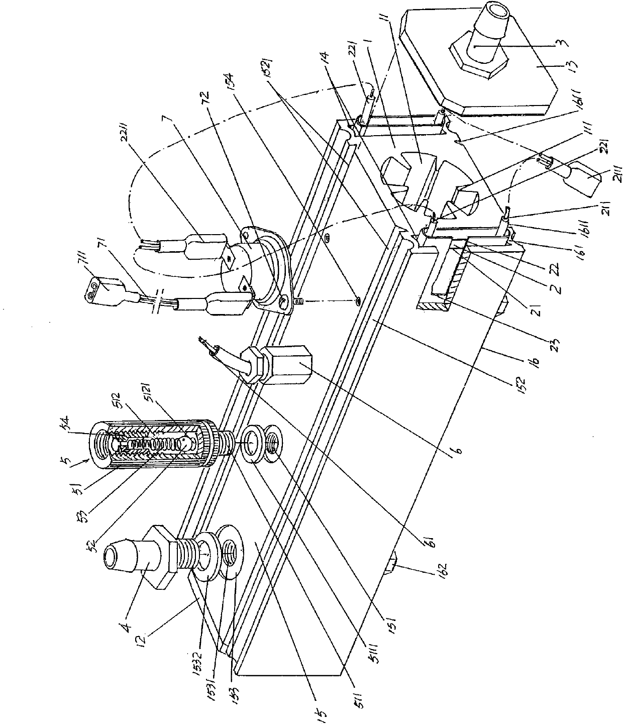
[0022] In the following descriptions, all directional concepts such as up, down, left, right, front and back are aimed at figure 1 As far as the position status shown is concerned, the purpose is to facilitate the public to interpret, so it should not be construed as a limitation on the solution of the present invention.

[0023] See figure 1 , a heater body 1 preferably made of a material with good heat con...


PUM


Abstract

The invention relates to a PTC liquid heater and belongs to the technical field of liquid heating devices. The PTC liquid heater comprises a heater body, a liquid inlet interface and a liquid outlet interface, wherein a liquid heating cavity is formed at the center of the heater body, a left sealing cover and a right sealing cover are arranged at the left end and the right end of the heater body in a matched mode, PTC element mounting cavities are respectively formed on a front side wall and a rear side wall of the heater body, and PTC elements are arranged in the mounting cavities. The liquid inlet interface is arranged on the right sealing cover and communicated with the liquid heating cavity, the liquid outlet interface is arranged on one of the left sealing cover and a top wall of the heater body, and a bottom wall of the heater body forms a heater body mounting wall. The PTC liquid heater is characterized in that a group of heating cavity cooling fins protruded out of a cavity wall surface of the liquid heating cavity are formed on the cavity wall of the liquid heating cavity at intervals in the length direction along the length direction of the liquid heating cavity. The PTC liquid heater is good in heat dissipation effect and high in heating efficiency, saves energy and materials, prevents the heater body from bursting, is safe to use, does not damage the PTC elements when pressing a cavity top wall and a cavity bottom wall and is good in intelligence effect.

Description

technical field [0001] The invention belongs to the technical field of liquid heating devices, and in particular relates to a PTC liquid heater, which is applied to cookers such as kitchen utensils such as range hoods, and provides support for a pipeline connected to it at one end and with a nozzle at the other end. The centrifugal impeller of the range hood implements hot water or steam for cleaning. Background technique [0002] The PTC mentioned above refers to a positive temperature coefficient thermistor, and the PTC liquid heater mentioned above refers to a heating facility that uses PTC to heat up liquid (mainly water). Technical information about PTC liquid heaters can be found in published Chinese patent documents, typically such as "A PTC Liquid Heater" recommended by Utility Model Patent Grant No. CN201476268U and "A PTC Liquid Heater" provided by CN201937849U ". The structural feature of these two patents is that a liquid heating cavity (the patent is called a ...

Claims


Application Information

Patent Timeline
Patent Type & Authority Applications(China)
IPC IPC(8): F24H1/18F24H9/18F24H9/20F22B1/28H05B3/00
Inventor 黄明峰
Owner 嘉善县魏塘资产管理有限公司
Why Eureka
Try Eureka