
Power supply device used for hollow cathode detection system

A technology of detection system and power supply device, which is applied in the field of electronics, can solve the problems of high excitation sensitivity, inability to meet the fast response of power supply, increase of reactive power loss, etc., and achieve the effect of realizing pulse current

Inactive Publication Date: 2014-04-23
AVIC BEIJING INST OF AERONAUTICAL MATERIALS
View PDF0 Cites 2 Cited by
  • Summary
  • Abstract
  • Description
  • Claims
  • Application Information

AI Technical Summary

Problems solved by technology

The DC power supply is generally designed as a DC stabilized voltage and current stabilized power supply, and the DC output voltage is above 800 volts. In fact, when the working gas is argon, the electric combustion voltage at which hollow cathode discharge can occur is about 600 volts. Too high output voltage makes no Power loss power increases, and it is unfavorable to operation safety
The discharge of the pulse power supply has the characteristics of high instantaneous power and large energy, so the excitation sensitivity is high, and the ideal spectral line blackness of the elements can be obtained with a small discharge current, but there will be problems of poor reproducibility caused by unstable discharge.
The power supply method of DC plus pulse has the characteristics of continuous and stable discharge and high energy instantaneous excitation. This kind of power supply has a simple structure, but the current regulation performance is relatively poor, which cannot meet the requirements of fast response of the power supply.

Method used


Image

  • Power supply device used for hollow cathode detection system

Examples


Embodiment Construction

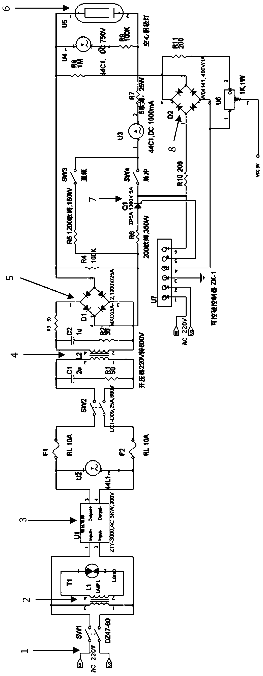
[0011] The technical scheme of the present invention will be described in further detail below in conjunction with accompanying drawing and embodiment:

[0012] See attached figure 1 As shown, the power supply device for the hollow cathode detection system is characterized in that: in this device, the 220V AC power supply 1 passes through the filter 2 and the voltage stabilizer 3, and then outputs to the booster 4 to boost the voltage to 600V-700V AC , and then converted into a DC voltage by the bridge rectifier Ⅰ5, the DC voltage is divided into two paths, one path is directly output to the hollow cathode lamp 6, and the other path generates a pulse current through the thyristor 7 and is output to the hollow cathode lamp 6, in addition, the hollow cathode The working current of the lamp 6 is output to the control signal input terminal of the thyristor 7 through the bridge rectifier Ⅱ 8, pin 4 and pin 6;

[0013] The power of 220V AC power supply 1, voltage regulator 2 and bo...


PUM


Abstract

The invention is a power supply device used for a hollow cathode detection system. In the power supply device, a 220V alternating current power (1) is output to a booster (4) to be boosted to an alternating current power of 600V-700V via a filter (2) and a voltage stabilizer (3), then the alternating current power of 600V-700V is converted into direct current voltage via a bridge type rectifier I (5), then the direct current voltage is divided into two paths, one path of the direct current voltage is directly output to a hollow cathode lamp (6), the other path of the direct current voltage generates pulse current via a silicon controlled rectifier (7) and then the pulse current is output to the hollow cathode lamp (6), and in addition, the working current of the hollow cathode lamp (6) is output to control signal input ends of the silicon controlled rectifier (7), four pin and six pin, via a bridge type rectifier II (8). Compared with the prior art, the power supply device adopts a direct current-and-pulse current combined power supply system. The pulse current is generated in wave absorption by a single silicon controlled rectifier parallelly connected in a combined circuit. The power supply device is advantaged in that power supply capacity is large, excitation intensity is strong, and a low detecting limit of detected elements of below ppm grade is achieved.

Description

technical field [0001] The invention relates to a power supply device for a hollow cathode detection system, which belongs to the field of electronic technology. Background technique [0002] Hollow cathode light source is a special form of spectral analysis light source. Utilizing the principle of low-pressure discharge, the energy is concentrated inside the cavity of the hollow cathode to the greatest extent, so it has the characteristics of high excitation intensity and high sensitivity. [0003] For nearly half a century, hollow cathode discharge has been widely used in emission spectroscopic analysis, especially ultrapure physical analysis. It has been proved from theoretical analysis and practice that hollow cathode discharge spectroscopic analysis has a lower detection limit than other spectral light sources in analyzing trace elements with low melting point and some trace elements with medium melting point. [0004] The power supply of hollow cathode light source g...

Claims


Application Information

Patent Timeline
IPC IPC(8): H05B37/02G01J3/10
Inventor 王宝如李帆杨春晟宋晓辉杨党纲
Owner AVIC BEIJING INST OF AERONAUTICAL MATERIALS
Learn More