Two-stage supercharging vehicle-mounted air compressor

An air compressor and two-stage supercharging technology, which is applied in mechanical equipment, machines/engines, liquid variable capacity machinery, etc., can solve the problems of reducing the service life of air compressors, inconsistent installation dimensions, and damage to piston rings, etc., to achieve Improved exhaust efficiency, reduced power consumption, and high exhaust pressure

Inactive Publication Date: 2014-04-30
GUANGXI YUCHAI MASCH CO LTD
View PDF12 Cites 6 Cited by
  • Summary
  • Abstract
  • Description
  • Claims
  • Application Information

AI Technical Summary

Problems solved by technology

[0004] 1. With the increase of exhaust pressure, the exhaust efficiency of single-stage air compressor gradually decreases. When the exhaust pressure rises to 12Bar, the exhaust efficiency is about 50%, resulting in high engine power consumption;
[0005] 2. The exhaust temperature of the single-stage air compressor exceeds 200°C. The high temperature will easily cause thermal deformation of the piston assembly of the air compressor, which will increase the partial wear of the piston and the amount of oil discharged with the air, resulting in high-temperature deformation of the cylinder liner and damage to the piston ring. Make the air compressor easy to leak oil, reduce reliability, and cause engine failure;
[0006] 3. The single-stage air compressor is often operated under high-load conditions, which not only greatly reduces the service life of the air compressor, but also increases the power consumption of the engine
Its disadvantages are: only one level of compression, low efficiency, high engine power consumption
Its shortcomings are: 1. The structure is complex, which is inconsistent with the installation size of the existing air compressor, which is not conducive to the transformation of the existing automobile braking system; 2. Compressed air is cooled by heat dissipation, resulting in high temperature, which is easy to cause high-temperature deformation of the cylinder liner Damaged piston rings increase the failure of the air compressor

Method used


Image

  • Two-stage supercharging vehicle-mounted air compressor
  • Two-stage supercharging vehicle-mounted air compressor
  • Two-stage supercharging vehicle-mounted air compressor

Examples


Embodiment 1

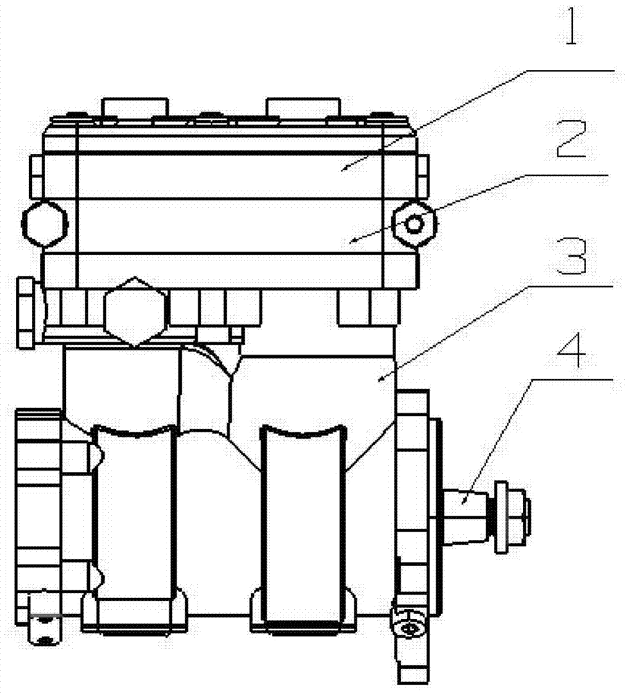
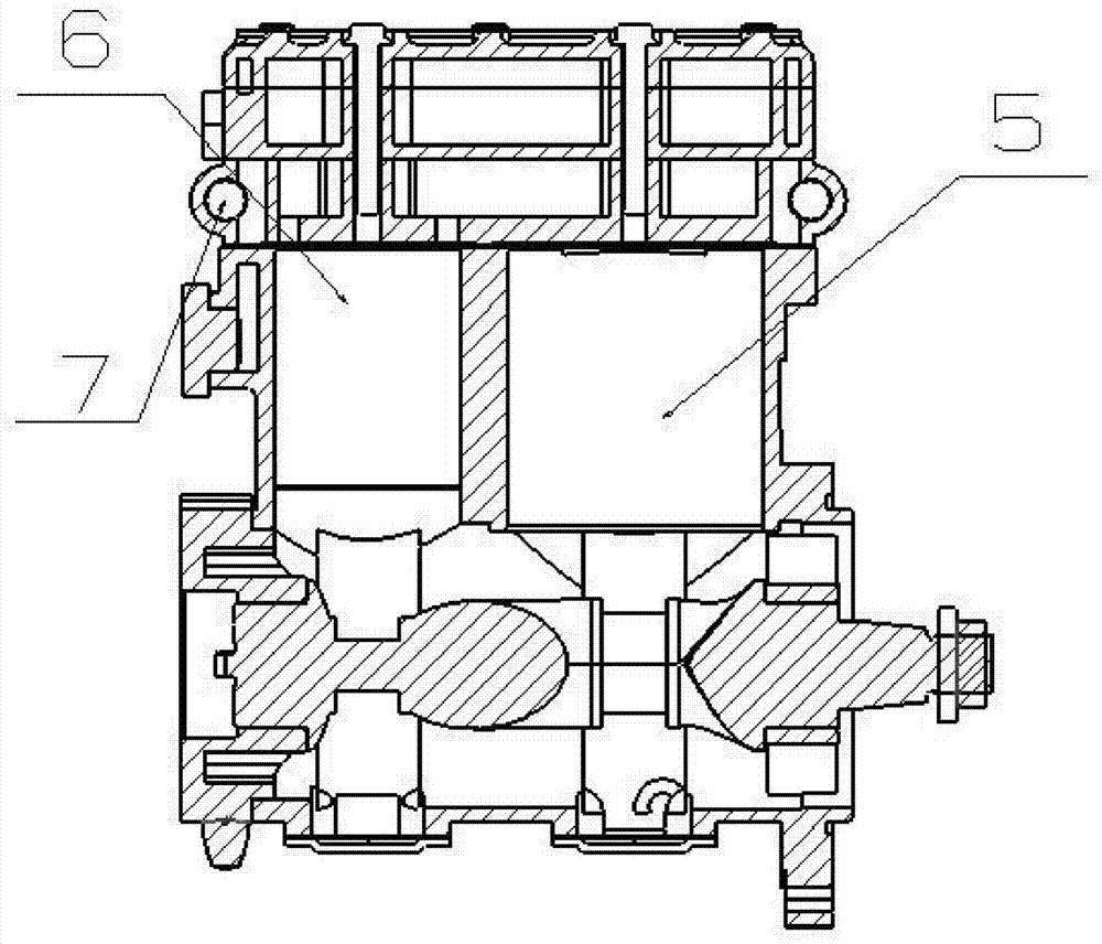
[0032] Such as figure 1 As shown, the present invention includes a cylinder head 1, the cylinder head 1 and the cylinder body 3 are connected through a valve plate assembly 2, a crankshaft 4 is arranged under the cylinder body 3, and a first-stage cylinder 5 and a second-stage cylinder are arranged side by side in the cylinder body 3 6. The valve plate assembly 2 is provided with an unloading mechanism 7 .

[0033] In this embodiment, during the working process, the compression process is equally distributed in the secondary compression process, that is, after the first stage 5 primary compression process is completed, the primary exhaust gas will be used as the intake air for the secondary compression, and will be used by the secondary compression process. The secondary cylinder 6 is repressurized by the secondary compression system and finally discharged to the air storage tank. Through the secondary pressurization inside the system, the demand for high exhaust pressure can...

Embodiment 2

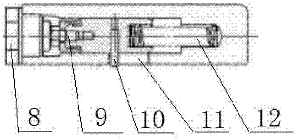
[0035] The difference from Embodiment 1 is that the unloading mechanism 7 includes an unloading hole 8, a plunger 9, a pin 10, a rack 11, a spring 12 and a gear 13, and the plunger 9 is fixedly connected to the rack 11 through the pin 10, One end of the plunger 9 is facing the unloading hole 8 , the other end is connected with the spring 12 , and the rack 11 is engaged with the gear 13 .

[0036] In this embodiment, the gear 13 is driven by the plunger 9 and the rack 11, and finally drives the movement of the unloading valve plate to realize the opening and closing of the unloading hole 8. By sealing the gear 13, the working chamber of the air compressor is completely isolated With the working chamber of the unloading plunger, this structure makes up for the defect that the working chamber of the air compressor in the original rack and ring gear structure is indirectly connected with the working chamber of the plunger, so that there is pressure gas at the tail of the plunger, w...

Embodiment 3

[0038] The difference from Embodiment 2 lies in that the cylinder head 1 is provided with a cooling system, and the gas compressed and discharged from the first-stage cylinder 5 enters the second-stage cylinder 6 after being cooled by the cooling system.

[0039] In this embodiment, after the first-stage compression process of the first-stage cylinder 5 is completed, the first-stage exhaust gas will be used as the intake air of the second-stage compression after being cooled between the stages, and will be repressurized by the second-stage cylinder 6 and the second-stage compression system. The temperature of the secondary exhaust can be lowered, ie the initial temperature of the final exhaust output is lowered.


PUM


Abstract

The invention discloses a two-stage supercharging vehicle-mounted air compressor and aims at providing an automotive two-stage supercharging air compressor which is low in power consumption, high in reliability and low in exhaust temperature. The two-stage supercharging vehicle-mounted air compressor comprises a cylinder cover, wherein the cylinder cover is connected with a cylinder body through a valve plate assembly, a crankshaft is arranged under the cylinder body, a primary air cylinder and a secondary air cylinder are arranged in the cylinder body in parallel, and an unloading mechanism is arranged on the valve plate assembly and comprises an unloading hole, a plunger piston, a pin, a rack, a spring and gear. The plunger piston is fixedly connected with the rack through the pin, one end of the plunger piston faces the unloading hole, the other end of the plunger piston is connected with the spring, the rack is meshed with the gear, a cooling system is arranged in the cylinder cover, air discharged by the primary air cylinder is cooled by the cooling system and then flows into the secondary air cylinder. The two-stage supercharging vehicle-mounted air compressor is suitable for modification of brake systems of large automobiles and existing automobiles.

Description

technical field [0001] The invention relates to the field of air compressors, in particular to a two-stage supercharging vehicle-mounted air compressor. Background technique [0002] The braking system of large cars mostly uses air brakes as an auxiliary to increase the braking force. The air compressor is the first energy supply device in the braking system, directly providing the air required by the braking system and generating the air pressure required for braking. . [0003] Most of the existing vehicle air compressors use ordinary single-stage air compressors. Due to their own structural limitations, ordinary single-stage air compressors have the following problems: [0004] 1. With the increase of exhaust pressure, the exhaust efficiency of single-stage air compressor gradually decreases. When the exhaust pressure rises to 12Bar, the exhaust efficiency is about 50%, resulting in high engine power consumption; [0005] 2. The exhaust temperature of the single-stage a...

Claims


Application Information

Patent Timeline
Patent Type & Authority Applications(China)
IPC IPC(8): F04B41/06F04B39/06
Inventor 丘道龙沈琼刘益军邓斌
Owner GUANGXI YUCHAI MASCH CO LTD
Why Eureka
Try Eureka