Mask plate and through hole forming method
A mask and via technology, used in the display field, can solve the problems of limited size, difficult to break through the exposure size, and restrict the application of resin vias, and achieve the effects of minimized vias, clear graphic edges, and good uniformity.
- Summary
- Abstract
- Description
- Claims
- Application Information
AI Technical Summary
Problems solved by technology
Method used
Image
Examples
Embodiment 1
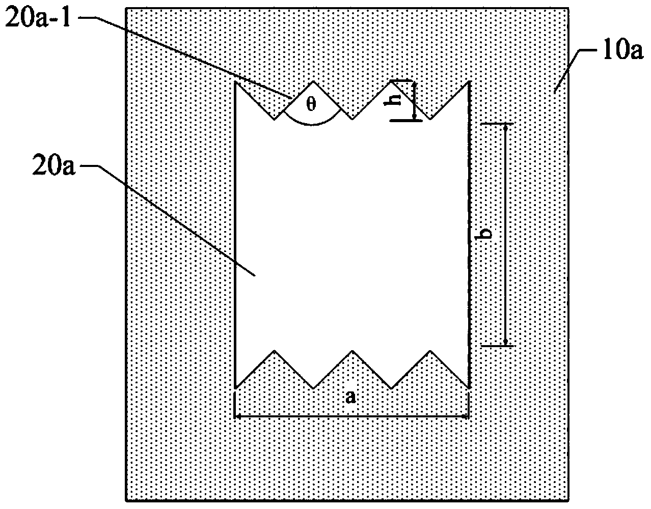
[0033] Such as figure 2 As shown, a mask plate according to an embodiment of the present invention has a light-transmitting pattern 20a on the mask plate 10a. In the light-transmitting pattern 20a, only one set of opposite sides is serrated, and the entire serrated side 20a- 1's sawtooth height h is equal.
[0034] In this embodiment, the angle θ of the tooth tip angle of the sawtooth on the side of the light-transmitting pattern can be 30-45°, preferably 45°; the light-transmitting pattern 20a is a square hole, and the size of the square hole is length a×width b 3 μm×3 μm; the sawtooth height h of the entire sawtooth-shaped side 20 a - 1 is 0.5 μm.
[0035] In this embodiment, the opposite sides of the light-transmitting pattern are set as zigzag, which can increase the exposure of the overall pattern. Since the size of the zigzag side is much smaller than the resolution of the exposure machine, the positive light of the zigzag part The resist or positive photosensitive re...
Embodiment 2
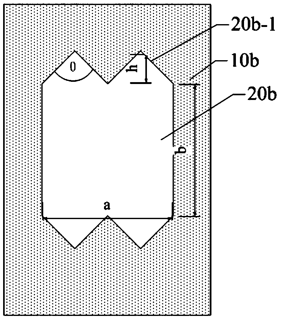
[0037] Such as image 3 As shown, in a mask plate of this embodiment, the mask plate 10b has a light-transmitting pattern 20b, and in the light-transmitting pattern 20b, only one set of opposite sides is saw-toothed, and the entire saw-toothed side 20b-1 is saw-toothed The heights h are equal, and the transparent pattern 20b in this embodiment is a square hole. The transparent pattern 20b has a sawtooth-shaped side 20b-1.
[0038] The angle θ of the sawtooth tooth tip angle of the sawtooth edge in this embodiment can be 30-45°, preferably 45°; the length a×width b of the light-transmitting pattern 20b is 3 μm×3 μm; the entire zigzag side The sawtooth height h of 20b-1 was 0.75 μm.
[0039] In this embodiment, the opposite sides of the light-transmitting pattern are set as zigzag, which can increase the exposure of the overall pattern. Since the size of the zigzag side is much smaller than the resolution of the exposure machine, the positive photolithography of the zigzag part...
Embodiment 3
[0041] Such as Figure 4 with Figure 5 As shown, in the mask provided by this embodiment, the mask 10c has a light-transmitting pattern 20c, and the edges of the light-transmitting pattern 20c are all jagged.
[0042] in, Figure 4 The light-transmitting pattern in is circular hole-shaped, while Figure 5 The light-transmitting pattern in is a square hole shape, Figure 5 The middle serrated side 20c-1 has four. The angle θ of the addendum angle of the sawtooth on the edge of the light-transmitting pattern can be 30-45°, preferably 40°; the diameter d of the circular-hole-shaped light-transmitting pattern is 3 μm; the size (length) of the square-hole-shaped light-transmitting pattern a×width b) is 3 μm×3 μm; the sawtooth height h of the entire sawtooth-shaped edge is 0.5 μm.
[0043] The edges of the light-transmitting pattern in this embodiment are all jagged mask plates, which can also increase the exposure of the overall pattern. Since the size of the jagged edges is ...
PUM
| Property | Measurement | Unit |
|---|---|---|
| diameter | aaaaa | aaaaa |
| size | aaaaa | aaaaa |
Abstract
Description
Claims
Application Information
 - R&D
- Intellectual Property
- Life Sciences
- Materials
- Tech Scout
- Unparalleled Data Quality
- Higher Quality Content
- 60% Fewer Hallucinations
Browse by: Latest US Patents, China's latest patents, Technical Efficacy Thesaurus, Application Domain, Technology Topic, Popular Technical Reports.
© 2025 PatSnap. All rights reserved.Legal|Privacy policy|Modern Slavery Act Transparency Statement|Sitemap|About US| Contact US: help@patsnap.com


