Current detection circuit module

A current detection circuit and detection circuit technology, applied in the direction of measuring current/voltage, only measuring current, voltage/current isolation, etc., can solve the problems of weak resistance to mechanical shock and large driving shock, and achieve improved mechanical shock resistance. The effect of simplifying the inspection process and increasing the degree of freedom

Inactive Publication Date: 2014-04-30
HONDA MOTOR CO LTD
View PDF10 Cites 17 Cited by
  • Summary
  • Abstract
  • Description
  • Claims
  • Application Information

AI Technical Summary

Problems solved by technology

[0021] However, since the magnetic core is provided outside the substrate, it becomes a structure weak against mechanical shock
In particular, since the impact caused by driving is large in electric vehicles, it is desired to enhance the mechanical shock resistance during driving, so there is a problem that it cannot be used in electric vehicles

Method used


Image

  • Current detection circuit module
  • Current detection circuit module
  • Current detection circuit module

Examples


Embodiment Construction

[0069] Hereinafter, embodiments of the present invention will be described with reference to the drawings.

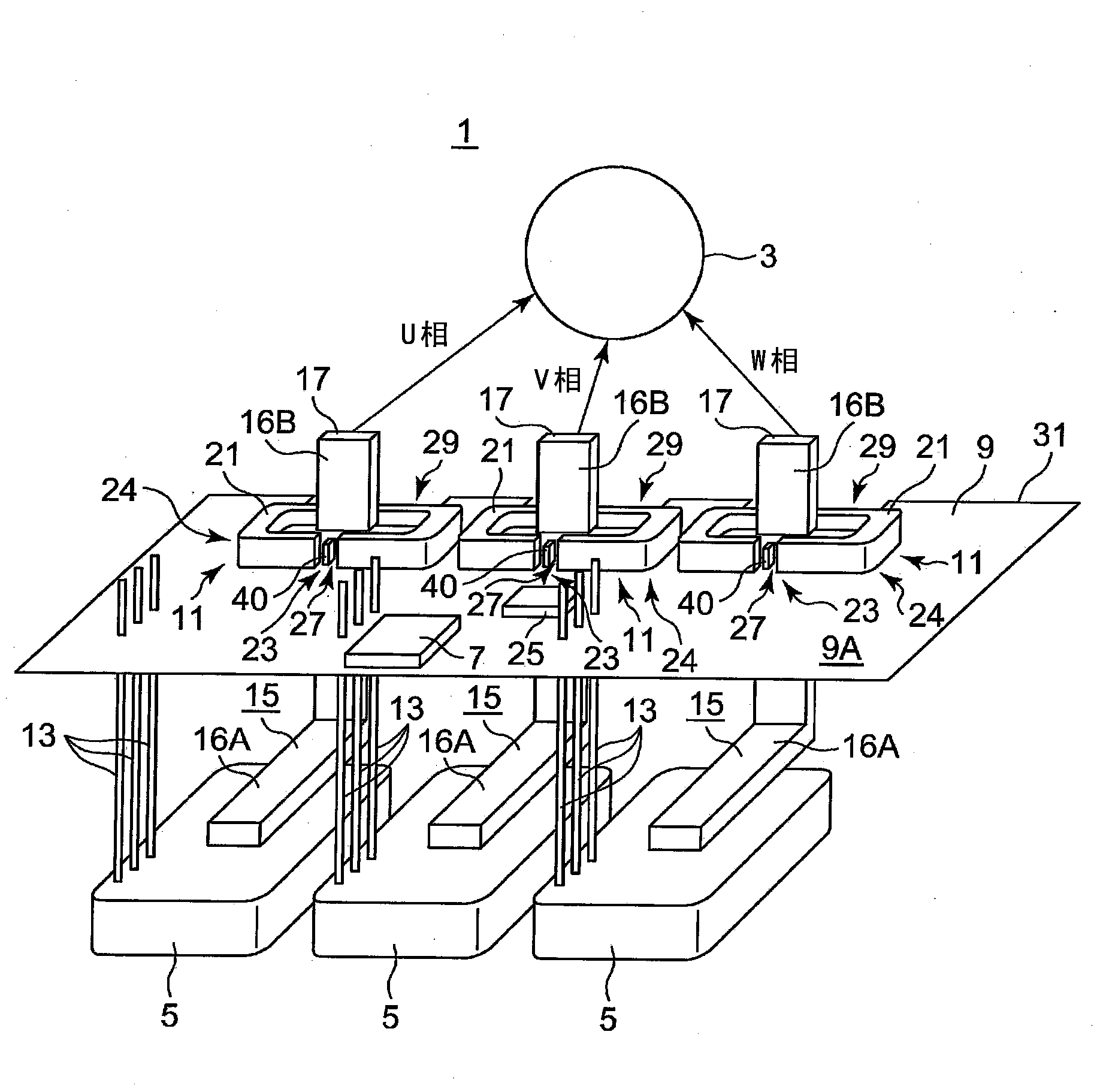
[0070] figure 1 It is a figure which schematically shows the structure of the three-phase inverter circuit module 1 which concerns on this embodiment.

[0071] The three-phase inverter circuit module 1 is installed in an electric vehicle such as an electric car, and controls a driving motor or a generator (hereinafter, they are referred to as "three-phase rotating electric machines" and given symbol 3), as shown in figure 1 As shown, it includes: a power module 5 , a control IC 7 , a control circuit board 9 on which the control IC 7 is mounted, and a current detection circuit module 11 mounted on the control circuit board 9 together with the control IC 7 .

[0072] The power module 5 includes, for example, a pair of switching elements (see Figure 13 ) is modularized into a package, and is set according to each phase of the three phases. The configuration of the pow...


PUM


Abstract

Provided is a current detection circuit module wherein it is possible to correct the current detection sensitivity before assembling a finished product and to achieve high mechanical shock resistance. A current detection circuit module (11) provided with a control circuit board (9) on which a control IC (7) for controlling power modules (5) is mounted, magnetic cores (21) which each have a gap (27) on a portion thereof and which surround busbars (15) extending from the power modules (5), magnetic detection elements (40) which are disposed within the gaps (27), and a detection circuit (44) which outputs to the control IC (7) the detection signal of the current value flowing through the busbars (15) in response to the output of the magnetic detection elements (40), wherein the detection circuit (44) is mounted on the control circuit board (9), the control circuit board (9) is provided with passing parts (29) which are formed by notches and which are used to arrange the busbars (15) perpendicular to the board surface, the magnetic cores (21) are mounted on the control circuit board (9) so as to surround the respective busbars (15) passing the respective passing parts (29), and the magnetic detection elements (40) are mounted on the control circuit board (9) such that the magnetic detection elements (40) are located within the gaps (27) of the respective magnetic cores (21).

Description

technical field [0001] The invention relates to a current detecting circuit module for detecting the current flowing in the current wire. Background technique [0002] In an electric vehicle, a three-phase inverter circuit module for controlling a drive motor or a generator is mounted. In addition, in the following description, when there is no need to distinguish between a drive motor and a generator, they are referred to as three-phase rotating electrical machines. [0003] Generally, such as Figure 13 As shown, the three-phase inverter circuit module 80 includes: a three-phase inverter circuit 82 as a power module for driving a three-phase rotating electric machine 81; A smoothing capacitor 84 for voltage stabilization; a three-phase inverter control circuit section 85 that controls the above-mentioned three-phase inverter circuit 82; and a current flowing in the three-phase rotating electrical machine is detected and output to the three-phase inverter control circuit s...

Claims


Application Information

Patent Timeline
Patent Type & Authority Applications(China)
IPC IPC(8): G01R15/20G01R19/00H02M7/00
CPCH02M2001/0009G01R19/0092H02M7/003G01R15/207H02M1/0009
Inventor 山口和彦山村拓也
Owner HONDA MOTOR CO LTD
Why Eureka
Try Eureka