Counter-flow closed-type cooling tower

A closed cooling tower and counter-flow technology, which is applied to water shower coolers, direct contact heat exchangers, heat exchange equipment, etc., can solve the problems of inability to change water volume, ice hanging on air inlet shutters, and easy blockage of air ducts, etc. , to achieve the effect of reducing the risk of icing, reducing evaporation consumption, and eliminating the phenomenon of white fog

Active Publication Date: 2014-05-07
YANTAI EBARA AIR CONDITIONER +1
View PDF9 Cites 15 Cited by
  • Summary
  • Abstract
  • Description
  • Claims
  • Application Information

AI Technical Summary

Problems solved by technology

The white mist has a great impact on the surrounding environment of the cooling tower, which may cause the ground near the cooling tower to freeze, causing certain safety hazards. In addition, the white mist will also dissolve ions in the air, making it acidic or alkaline and corroding nearby objects
[0004] 2. The existing cooling towers are generally designed according to the wet bulb temperature in summer. When used in winter, due to the decrease of the external environment temperature, if the cooling tower still maintains full-load operation, its actual cooling capacity exceeds the required capacity, which will cause water leakage. Massive waste of resources and energy
[0005] 3. In some colder areas, cooling towers with air inlet louvers often have ice hanging on the air inlet louvers. This is generally because they do not control the spray area of ​​the spray water, resulting in water flowing or splashing When it reaches the air intake louvers and freezes, it is easy to block t

Method used


Image

  • Counter-flow closed-type cooling tower
  • Counter-flow closed-type cooling tower
  • Counter-flow closed-type cooling tower

Examples


Embodiment Construction

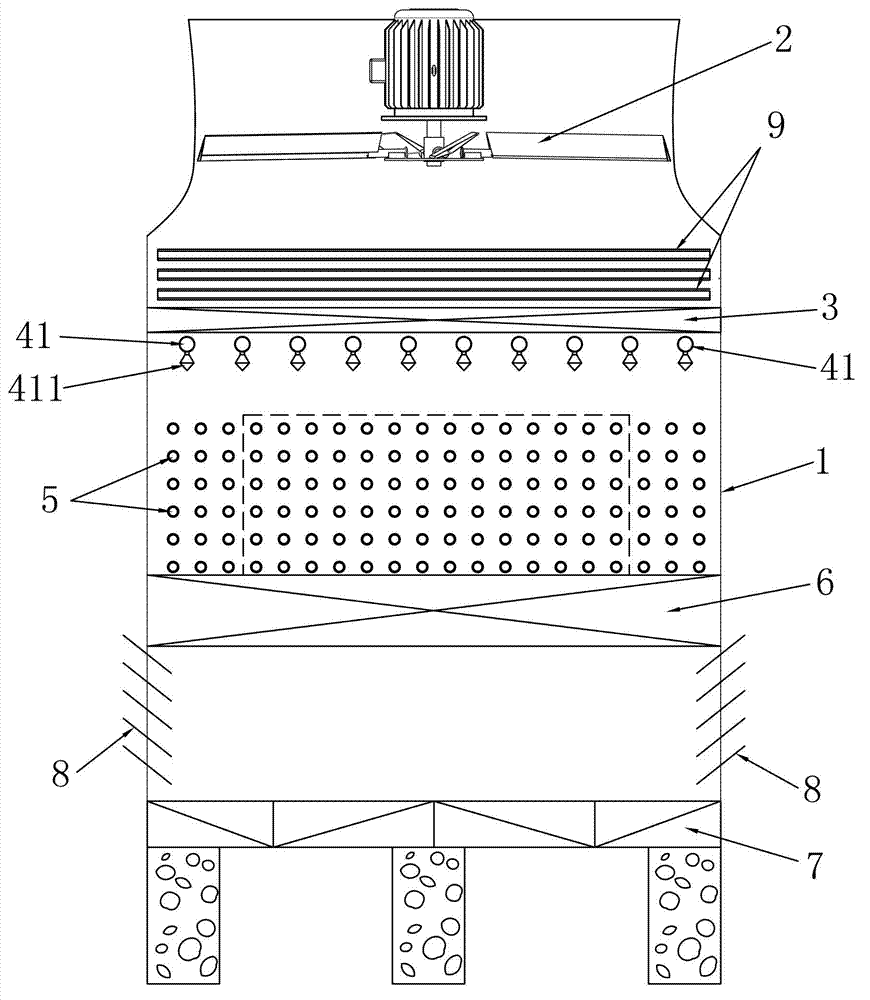
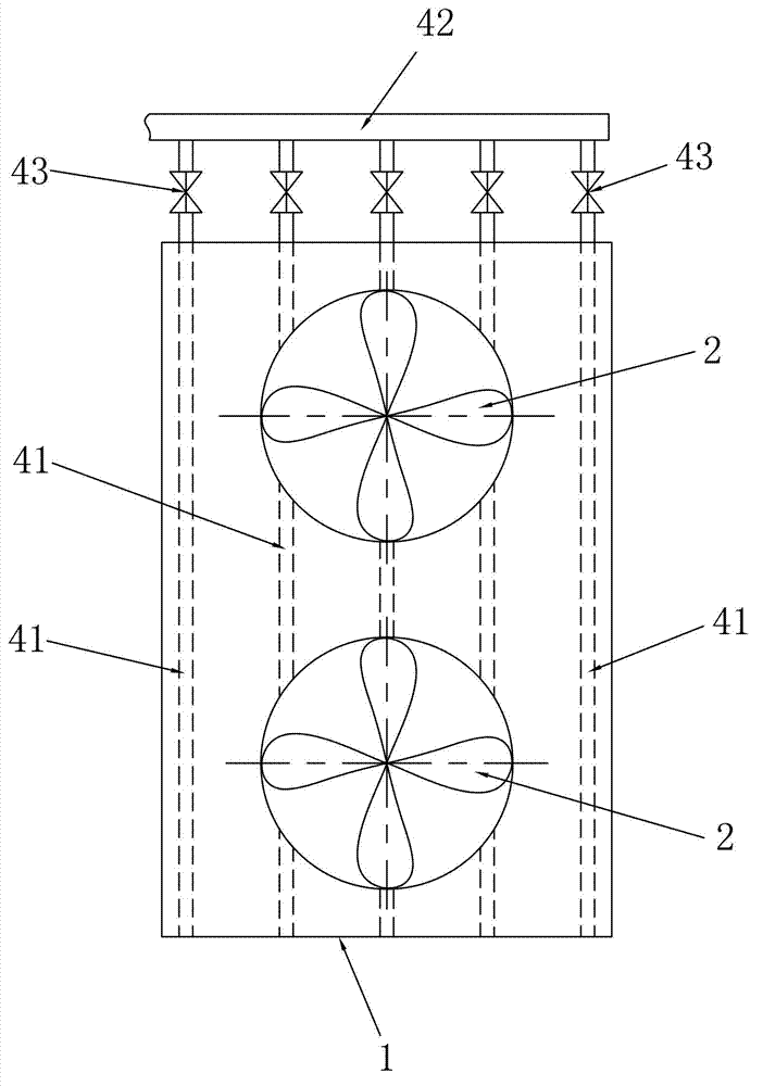
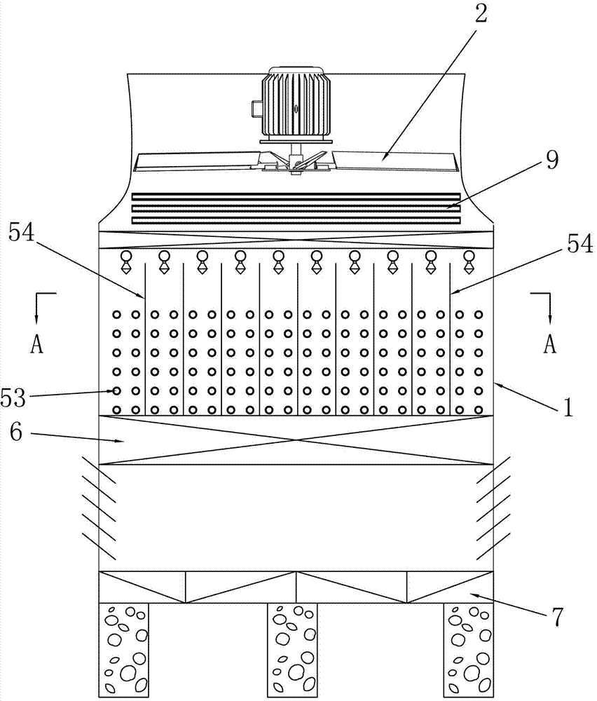
[0027] like figure 1 As shown, like the prior art, the first embodiment of the counterflow closed cooling tower of the present invention includes a tower body 1, and the tower body 1 is respectively provided with a fan 2, a water eliminator 3, a water distribution device, The first heat exchanger 5, filler 6 and water collection tank 7, the side wall of the tower body 1 is provided with an air inlet, the air inlet is located between the filler 6 and the water collection tank 7, and the air inlet is provided with an air inlet louver 8, which is similar to the existing The technical difference is: the tower body 1 is also provided with a second heat exchanger 9, the second heat exchanger 9 is located between the fan 2 and the water eliminator 3, the second heat exchanger 9 is connected to the first heat exchanger 5 In addition, the water distribution device in this embodiment includes ten water distribution pipes 41, each water distribution pipe 41 is distributed from the middle...


PUM


Abstract

The invention discloses a counter-flow closed-type cooling tower, belongs to heat exchanging equipment, particularly relates to a closed-type cooling tower which is used for preventing fogging at an air outlet, and aims to provide a counter-flow closed-type cooling tower which, during winter operation, can alleviate or eliminate fogging at the air outlet and reduce the risk of ice formation at shutters of the air outlet, and is convenient to save water. The counter-flow closed-type cooling tower comprises a tower body (1), a blower (2), a water collector (3), a water distributing device, a first heat exchanger (5), filling (6), a water collecting groove (7), air inlet shutters (8), a second heat exchanger (9), and a main water collecting pipe (42), wherein the water distributing device comprises a plurality of water distributing pipes (41); all the water distributing pipes are distributed in the tower from the middle to two sides in parallel to one another, or are distributed in the tower from the center to the periphery; a plurality of water distributing nozzles (411) are arranged on the side wall below the water distributing pipes; each water distributing pipes is connected with the main water collecting pipe through a flow rate adjustable valve (4).

Description

technical field [0001] The invention relates to a heat exchange device, in particular to a closed cooling tower for preventing fog formation at an air outlet. Background technique [0002] A cooling tower is a device that dissipates the waste heat generated in industrial production or refrigeration processes into the atmosphere. It can exchange heat with the air in the cooling medium (usually water) carrying waste heat, and transfer the heat of the medium. The medium is cooled by supplying air and dispersing into the atmosphere. Cooling towers are widely used in air conditioning cooling, refrigeration, plastic chemical industry and other industries. Cooling towers are generally composed of fillers (also known as heat dissipation materials), water distribution systems, ventilation equipment, air distribution devices (such as air inlet shutters, air guide devices, air ducts, etc.), water retainers (or water collectors) and water collection tanks ( or sump) etc. Existing coo...

Claims


Application Information

Patent Timeline
IPC IPC(8): F28C1/02F28C1/14F28F27/00
Inventor 赵昆姚金海王悦段永红大高诚
Owner YANTAI EBARA AIR CONDITIONER
Why Eureka
Try Eureka