Debris flow infrasound signal screening method, generation positioning method and path monitoring method

A screening method and technology for debris flow, applied in program control devices, special data processing applications, instruments, etc., can solve the problems of real-time monitoring of the movement process of inapplicable and inoperable flood sources, high construction costs, etc., and reduce the probability of false alarms. Effect

Inactive Publication Date: 2014-05-07
INST OF MOUNTAIN HAZARDS & ENVIRONMENT CHINESE ACADEMY OF SCI
View PDF0 Cites 12 Cited by
  • Summary
  • Abstract
  • Description
  • Claims
  • Application Information

AI Technical Summary

Problems solved by technology

[0005] If this method is applied to the monitoring and positioning of debris flow, there are at least five defects: 1. In this method, there is no screening of infrasound signals, but only band-pass filtering is performed to find the characteristic spectrum, and then after sub-band filtering, It is directly used for positioning to determine whether the wave source comes from the dam area, and its accuracy is greatly limited; 2. The disaster occurrence location that the method can realize is a relatively static point like the source of the dam flood discharge, and it cannot be applied to the debris flow faucet Such a moving object; 3. The result of the method is to obtain a statistical probability map from the direction of the wave to describe the source of infrasonic waves in different frequency bands under the same flood discharge, that is, only limit the location of the disaster to a certain geographical interval, and do not complete the accuracy Coordinate positioning, such as latitude and longitude coordinates; 4. Since no precise positioning is achieved, from the analysis of technical principles, this method cannot further realize real-time monitoring of the movement process of the source of flood discharge, so the technical effect is limited; 5. Dozens of Three sensors are arranged into a small sub-array, and then the sub-arrays are arranged according to certain rules, so the construction cost and system operation and maintenance require high costs

Method used


Image

  • Debris flow infrasound signal screening method, generation positioning method and path monitoring method
  • Debris flow infrasound signal screening method, generation positioning method and path monitoring method
  • Debris flow infrasound signal screening method, generation positioning method and path monitoring method

Examples


Embodiment 1

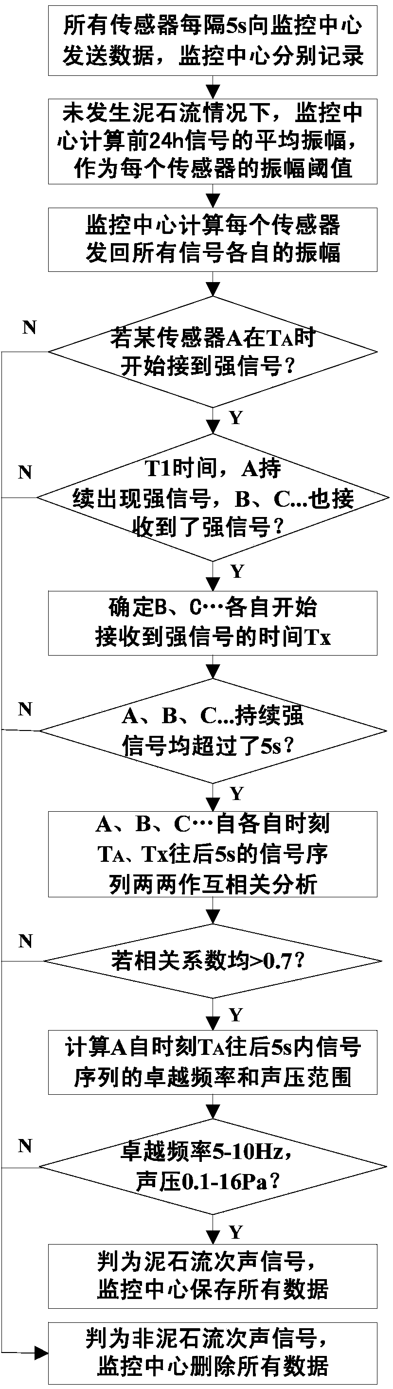
[0079] As shown in Figure 1, infrasound monitoring is carried out for the occurrence of debris flow in a certain debris flow basin, and the infrasound signal of debris flow is screened by the method of the present invention.

[0080] 1. Monitoring system layout

[0081] Determine three points A, B, and C around the debris flow basin. The coordinates are: point A (WGS84 geodetic coordinates: N26°16'59.96", E103°10'31.73"), point B (WGS84 geodetic coordinates: N26° 16'56.64", E103°11'26.89"), location C (WGS84 geodetic coordinates: N26°14'42.61, E103°8'4.22"). Convert the geodetic coordinates of the three points into Beijing 54 plane coordinates, respectively: Location A (2909549.78466876, 317751.599722409), location B (2909437.15689932, 319281.150755059), location C (2905390.78996434, 313597.0105219), the unit is m. Arrange an infrasound monitoring element at the three locations.

[0082] Each infrasound monitoring sensor element includes an infrasound receiving sensor, a sate...

Embodiment 2

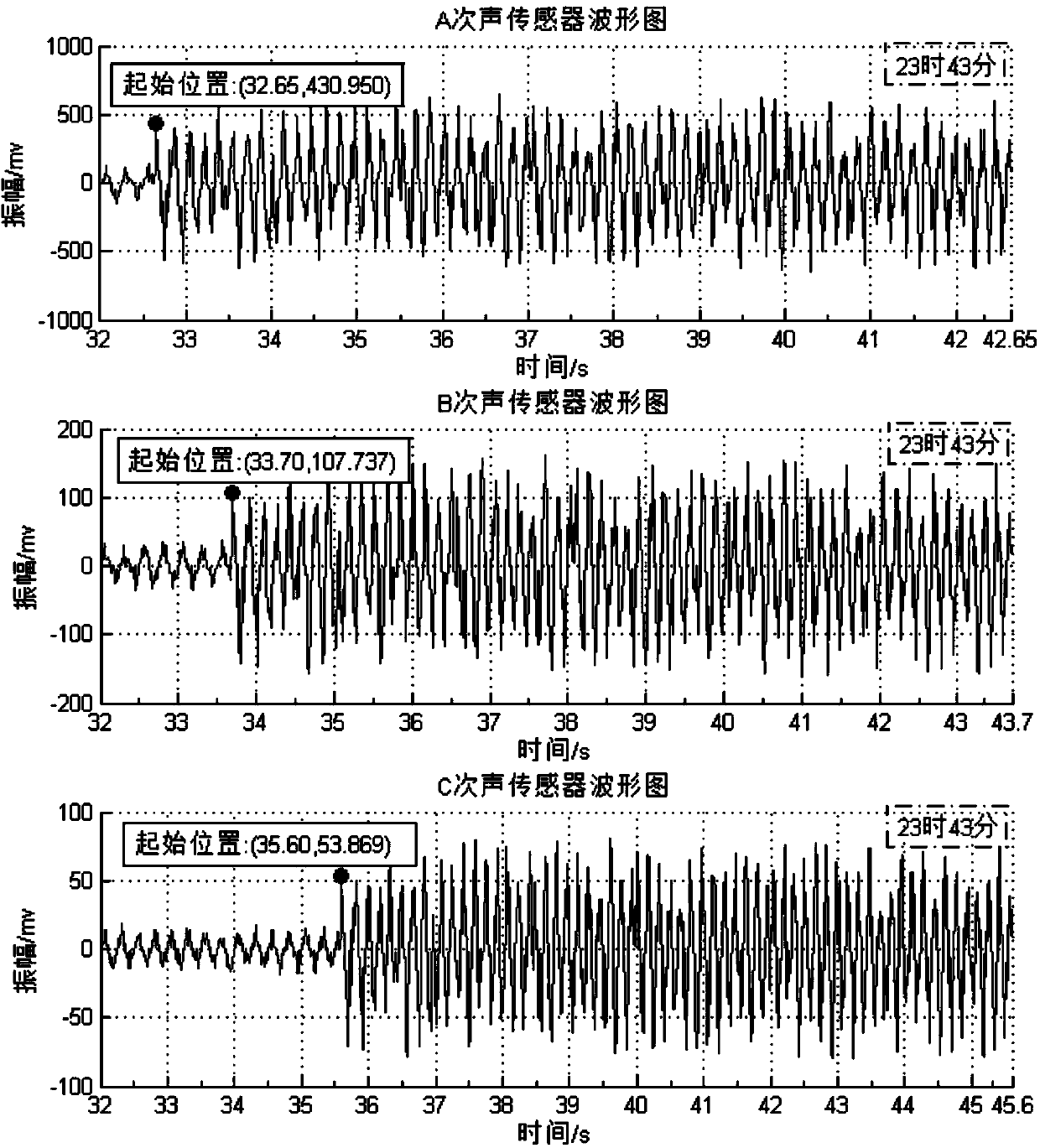
[0087] Such as diagram 2-1 As shown, on the basis of the screening and determination of debris flow occurrence signals completed in Embodiment 1, the method of the present invention is used to locate the debris flow occurrence site.

[0088] Scan all the amplitude-time waveform diagrams generated in the early stage of each acoustic monitoring sensor unit ( Figure 2-2 ), find out the time point corresponding to the first peak with the largest amplitude in each waveform diagram, which are: A point 23:43:33.375 seconds, B point 23:43:34.425 seconds, C point 23:43:36.325 seconds .

[0089] A point, B point, C point, the time difference between each point τ AB =1.050s, τ AC =2.950s, τ BC = 1.900s.

[0090] will τ AB =1.050s, τ AC =2.950s, τ BC = 1.900s, X A =2909549.78466876, Y A =317751.599722409, XB =2909437.15689932, Y B =319281.150755059, X C =2905390.78996434, Y C =313597.0105219 Substitute into formula 1 ~ formula 4, calculate and determine the plane coordinate...

Embodiment 3

[0092] Such as Figure 3-1 As shown, on the basis of completing the location of the debris flow in Embodiment 2, the whole movement of the debris flow is monitored in real time by the method of the present invention.

[0093] After accurately locating the location of the debris flow, during the follow-up movement of the debris flow, the infrasound monitoring sensor element at each location collects the infrasound data of the debris flow in real time and transmits it to the monitoring center. The real-time monitoring process of the debris flow path is as follows: Figure 3-1 shown.

[0094] Each sensor element sends an infrasound signal back to the monitoring center in real time, and the data period is 5s. The time point t used for the location of the debris flow in each sensor primitive data has been determined in the location of the debris flow in Example 2 A =23h43m33.375s, t B =23h43m34.425s, t C = 23h43m36.325s. Go to the following steps:

[0095] In step S310, the m...


PUM


Abstract

The invention discloses a debris flow infrasound signal screening method, a debris flow generation place positioning method and a debris flow motion path real-time monitoring method. Aiming at the defects that in the prior art, in the infrasound positioning process, signal screening is not carried out, signal identification accuracy is low, coordinates cannot be accurately positioned and the like, the invention provides the debris flow infrasound signal screening method. The method comprises the steps as follows: firstly, background noise interference is eliminated by four indexes of signal duration, signal relevance, a signal predominant frequency and a sound pressure and then a method of firstly and mainly analyzing an abnormal signal and then carrying out reference analysis on the abnormal signal is adopted to simultaneously process signals acquired by a plurality of sensors in two paths so as to ensure accuracy and high efficiency of screening debris flow generation signals. On the basis of the signal screening method, the invention also provides the debris flow generation positioning method which can realize accurate coordinate positioning on a debris flow generation site and further provides the debris flow motion path real-time monitoring method which can realize visual real-time monitoring on debris flow.

Description

technical field [0001] The invention relates to a debris flow infrasonic signal screening method and a method for locating a debris flow occurrence site and a real-time monitoring method for a debris flow movement path realized by using the same, belonging to the field of debris flow disaster reduction. Background technique [0002] During the formation and movement of debris flow, the rock layer will produce infrasound waves (referred to as infrasound) that propagate stably in the air and contain important geological information due to phenomena such as fracture, friction, extrusion, and impact on the ditch bed. The frequency, main frequency amplitude and duration of the infrasound signal emitted by the debris flow all have unique characteristics. The propagation speed of infrasound is only related to temperature, and has nothing to do with air density, pressure, etc., and its acoustic emission source is a spherical wave, which has no directionality. It can be transmitted a...

Claims


Application Information

Patent Timeline
Patent Type & Authority Applications(China)
IPC IPC(8): G06F19/00G06F9/44
Inventor 韦方强刘敦龙冷小鹏洪勇
Owner INST OF MOUNTAIN HAZARDS & ENVIRONMENT CHINESE ACADEMY OF SCI
Why Eureka
Try Eureka