
Ice preventing and removing system for aircraft wing

A wing and anti-icing technology, which is applied in the field of anti-icing system of aircraft wings, can solve the problem of consuming aircraft air source or electric energy, etc., and achieve the effect of simple structure and remarkable anti-icing effect

Inactive Publication Date: 2014-05-14
BEIHANG UNIV
View PDF5 Cites 17 Cited by
  • Summary
  • Abstract
  • Description
  • Claims
  • Application Information

AI Technical Summary

Problems solved by technology

The latter two systems are widely used. The main method is to draw hot air from the engine or arrange heating film / wire to heat the skin, which will consume valuable air source or electric energy on the aircraft.

Method used


Image

  • Ice preventing and removing system for aircraft wing

Examples


Embodiment Construction

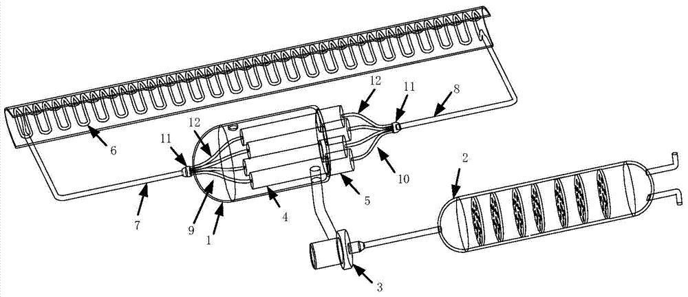
[0021] The anti-icing system of the present invention includes a heat source housing 1, an exhaust gas treatment device 2, an air pump 3, an evaporator 4, a liquid reservoir 5, a condenser 6, a steam line 7 and a liquid line 8, such as figure 1 shown.

[0022] Wherein, the heat source housing 1 adopts a cylindrical structure and is wrapped with heat-insulating material, which can reduce the heat dissipation of high-temperature gas to the outside and improve the utilization rate of heat. Let the two end faces of the heat source housing 1 be the end face A and the end face B respectively; resistance received. A waste gas inlet and a waste gas outlet are respectively opened on the side walls of the heat source housing 1 near the end surface A and the end surface B; and the waste gas inlet and the waste gas outlet are located on opposite sides of the heat source housing. The exhaust gas inlet is used to introduce engine exhaust gas; the engine exhaust gas is discharged into the ...


PUM


Abstract

The invention discloses an ice preventing and removing system for an aircraft wing. The system comprises a waste gas treatment device, an air pump, a shell, an evaporator, a condenser, an air line and a liquid line, wherein engine waste gas treated by the waste gas treatment device is introduced into the shell to heat the evaporator, working media are vaporized after being heated in the evaporator and then led out through the air line, and then the working media are cooled into liquid in the condenser located on the skin and give out heat, and finally flow back to the evaporator through the liquid line to finish the whole circulation. According to the system, the vapor-liquid two-phase flow phase change heat transfer design concept is adopted, vapor-liquid phase conversion of the working media is utilized to transmit heat, and then the purpose of preventing and removing ice on the aircraft wing is achieved; engine waste gas of an airplane is utilized as the heat source to increase the comprehensive utilization rate of airplane energy.

Description

technical field [0001] The invention belongs to the technical field of aircraft anti-icing, and in particular relates to an anti-icing system for aircraft wings. Background technique [0002] When an aircraft flies in a cloud layer containing supercooled water droplets, icing may occur on the wings and other parts. In severe cases, it will affect flight safety. Therefore, anti-icing systems must be installed on parts prone to icing. [0003] According to the different energy methods used in anti-icing, the existing anti-icing systems can be divided into mechanical anti-icing systems, liquid anti-icing systems, gas-heat anti-icing systems and electric heating anti-icing systems. The latter two systems are widely used. The main method is to draw hot air from the engine or arrange heating film / wire to heat the skin, which will consume valuable air source or electric energy on the aircraft. [0004] For piston engines, the exhaust gas discharged contains a large amount of heat ...

Claims


Application Information

Patent Timeline
Patent Type & Authority Applications(China)
IPC IPC(8): B64D15/04
Inventor 常世楠赵媛媛
Owner BEIHANG UNIV
Learn More