Hydraulic engineering vertical water stop structure and manufacturing and construction method thereof

A vertical water stop and water conservancy engineering technology, applied in water conservancy projects, underwater structures, sea area engineering, etc., can solve problems such as difficult cleaning, prolonging the construction period, and inability to pour continuously, so as to save installation procedures, reduce construction period, The effect of preventing cross-sectional interface misalignment

Inactive Publication Date: 2014-05-14
宋振利
View PDF5 Cites 24 Cited by
  • Summary
  • Abstract
  • Description
  • Claims
  • Application Information

AI Technical Summary

Problems solved by technology

[0002] In existing concrete structures, such as retaining dams, reservoirs, subways, culverts, sluices, tunnels and other underground projects, due to the inability to pour continuously or the deformation of the foundation settlement (earthquake), or the concrete caused by temperature changes Due to thermal expansion and contraction of components, deformation joints and construction joints are often left during pouring. These gaps must take anti-leakage measures to prevent external water or groundwater from leaking into the structural space. Concrete grooves are set between the concrete an

Method used


Image

  • Hydraulic engineering vertical water stop structure and manufacturing and construction method thereof
  • Hydraulic engineering vertical water stop structure and manufacturing and construction method thereof
  • Hydraulic engineering vertical water stop structure and manufacturing and construction method thereof

Examples


Embodiment

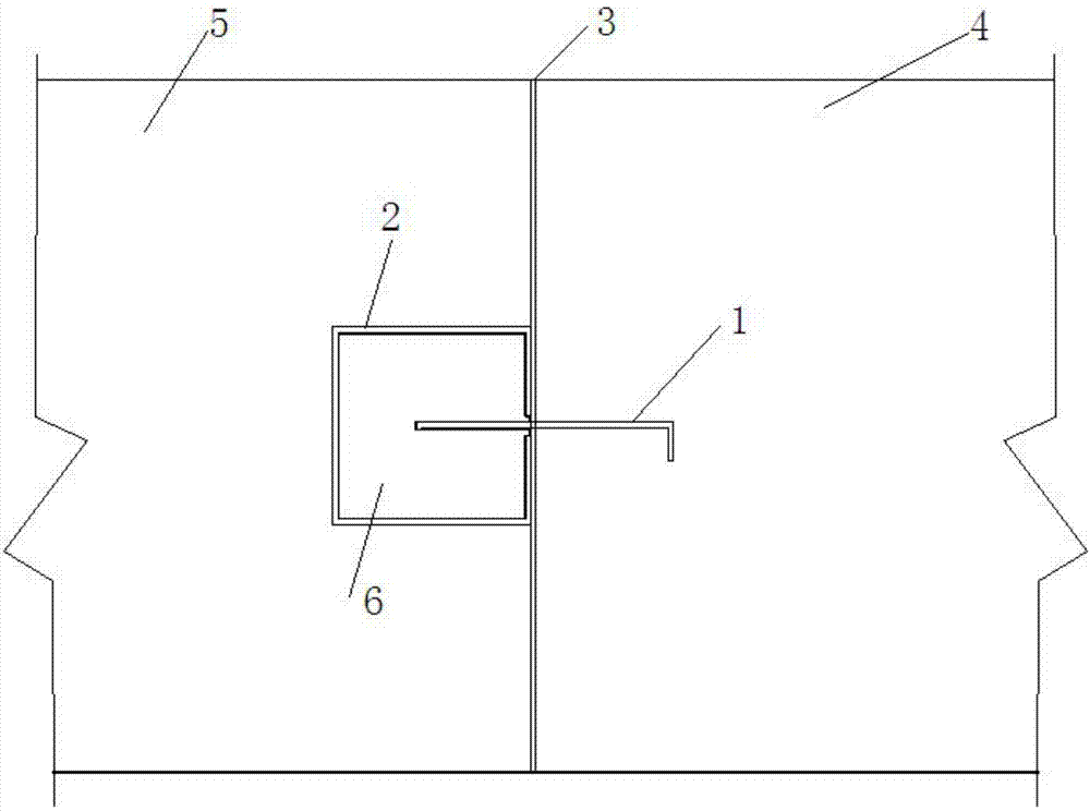
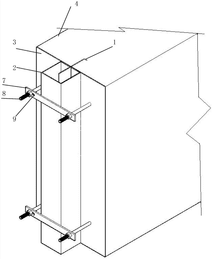
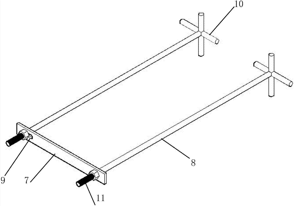
[0040] Embodiment, referring to the accompanying drawings: a vertical water stop structure for water conservancy projects, including a copper sheet 1, a channel steel 2 and a fixing device, one side of the copper sheet 1 is prefabricated in the first-stage concrete 4, and the other side is Protruding from the concrete section, it is placed in the channel steel opening 12, the copper sheet 1 extends into the channel steel 2 to a certain depth, and the channel steel 2 is provided with soft asphalt 6; the channel steel opening 12 surface and the first-stage concrete 4 section Asphalt felt 3 is arranged on both sides of the copper sheet 1, and one end of the fixing device is pre-embedded in the first-stage concrete 4, and the other end is arranged on both sides of the channel steel 2, and the channel steel 2 is fixed on the channel steel 2 by flat iron 7 and nuts Phase I concrete 4 sections.

[0041] Further, the thickness of the copper sheet 1 is 1-3mm, the width is 40-80cm, the ...


PUM

PropertyMeasurementUnit
Thicknessaaaaaaaaaa
Widthaaaaaaaaaa
Thicknessaaaaaaaaaa

Abstract

The invention discloses a hydraulic engineering vertical water stop structure and a manufacturing and construction method of the hydraulic engineering vertical water stop structure. The water stop structure comprises a red copper piece, a steel channel and a fixing device, wherein one side edge of the red copper piece is preburied in first-stage concrete, the other side edge of the red copper piece protrudes out of the fracture surface of the concrete and is arranged in an opening of the steel channel, and the red copper piece stretches into the steel channel by a certain depth; the portions, on the two sides of the red copper piece, of the opening face of the steel channel are provided with bituminous felt, and the portions, on the two sides of the red copper piece, of the fracture surface of the first-stage concrete are provided with bituminous felt; one end of the fixing device is preburied in the first-stage concrete, the other end of the fixing device is arranged on the two sides of the steel channel, the steel channel is fixed to the fracture surface of the first-stage concrete through band iron and nuts, after the steel channel is filled with maltha, the protruding part of the fixing device is cut, and then the steel channel is poured in second-stage concrete. The problem of water seepage caused by differential settlement or diastrophism of stratums in hydraulic engineering can be solved, manpower can be saved, and the construction period can be shortened.

Description

technical field [0001] The invention relates to an underground (underwater) building waterproof device, in particular to a vertical water-stop structure for water conservancy projects and its manufacturing and construction methods. Background technique [0002] In existing concrete structures, such as retaining dams, reservoirs, subways, culverts, sluices, tunnels and other underground projects, due to the inability to pour continuously or the deformation of the foundation settlement (earthquake), or the concrete caused by temperature changes Due to thermal expansion and contraction of components, deformation joints and construction joints are often left during pouring. These gaps must take anti-leakage measures to prevent external water or groundwater from leaking into the structural space. Concrete grooves are set between the concrete and the second-stage concrete, and soft asphalt and copper sheets or rubber waterstops are installed in the grooves. However, this method re...

Claims


Application Information

Patent Timeline
IPC IPC(8): E02D29/16E02D31/02
CPCE02B3/16E02D29/16E21D11/385
Inventor 张朝利
Owner 宋振利
Why Eureka
Try Eureka