Simple heat flow detection apparatus

A detection device, heat flow technology, applied in the direction of measuring device, measuring heat, volume/mass flow generated by electromagnetic effects, etc., can solve the problems of unwillingness to lower the temperature, not reduce the cost, keep high temperature, etc., and achieve low cost , high measurement sensitivity, and the effect of meeting production needs

Inactive Publication Date: 2014-05-14
XIAN DAOHENG TRANSPORTATION EQUIP TECHCO
View PDF0 Cites 8 Cited by
  • Summary
  • Abstract
  • Description
  • Claims
  • Application Information

AI Technical Summary

Problems solved by technology

[0003] Centralized heating is mostly used for heating in northern my country in winter, and each household is charged according to the area. However, some households do not need to turn on the heating very fully. They can lower

Method used


Image

  • Simple heat flow detection apparatus

Examples


Example Embodiment

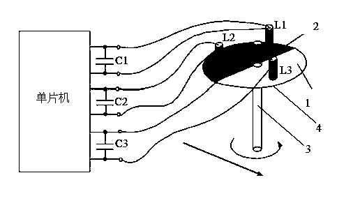
[0009] The present invention will be described in more detail below with reference to the drawings and embodiments.

[0010] As shown in the figure, the present invention is a simple heat flow detection device, including an LC resonant circuit composed of a capacitor C1 and an inductor L1, an LC resonant circuit composed of a capacitor C2 and an inductor L2, and a capacitor C3 and an inductor L3. The LC resonant circuit three, the LC resonant circuit one, the LC resonant circuit two, and the LC resonant circuit three are all connected to the single-chip microcomputer and the single-chip microcomputer provides excitation pulse signals. The inductors L1, L2, and L3 are distributed at equal intervals on the top of the disk 4. The disc 4 is coated with a metal film 2 in a semicircle, and a non-metal film 1 is coated in the other semicircle. The center of the disc 4 is connected to the rotating shaft 3.

[0011] The principle of the present invention is:

[0012] Through the rotation of ...


PUM


Abstract

Disclosed is a simple heat flow detection apparatus. The apparatus comprises a first LC resonance loop composed of a capacitor C1 and an inductor L1, a second LC resonance loop composed of a second capacitor C2 and a second inductor L2, and a third LC resonance loop composed of a capacitor C3 and an inductor L3. The first LC resonance loop, the second LC resonance loop and the third LC resonance loop are connected with a single-chip microcomputer and is provided with excitation pulse signals by the single-chip microcomputer; the inductors L1, L2 and L3 are distributed on a disc at equal intervals; on the disc, one semicircle is coated by a metal film, and the other semicircle is coated by a non-metal film; and the center position below the disc is connected with a rotating shaft. According to the invention, a nonmagnetic flowmeter is employed for realizing metering of heat quantity, the measuring sensitivity is high, the overall system structure is quite simple, the cost is quite low, and the production demand can be satisfied.

Description

[0001] technical field [0002] The invention relates to the technical field of heat flow detection, in particular to a simple heat flow detection device. Background technique [0003] Centralized heating is mostly used for heating in northern my country in winter, and each household is charged according to the area. However, some households do not need to turn on the heating very fully. They can lower the heating temperature through the valve at the terminal, but the corresponding cost But it has not been lowered, so some users would rather keep the high temperature than lower the temperature, which caused a lot of waste. Contents of the invention [0004] In order to overcome the shortcomings of the above-mentioned prior art, the purpose of the present invention is to provide a simple heat flow detection device, which has the characteristics of simple structure and convenient use. [0005] In order to achieve the above object, the technical scheme adopted in the present ...

Claims


Application Information

Patent Timeline
IPC IPC(8): G01K17/06G01F1/56
Inventor 不公告发明人
Owner XIAN DAOHENG TRANSPORTATION EQUIP TECHCO
Why Eureka
Try Eureka