
Device and method for measuring and correcting distortion of virtual reality displayer

A virtual reality and display technology, applied in the field of projection optical systems, can solve problems such as distortion of projected images, effects of projected images on viewing comfort, and misjudgment of important information.

Active Publication Date: 2014-05-14
深圳市安思疆科技有限公司
View PDF5 Cites 53 Cited by
  • Summary
  • Abstract
  • Description
  • Claims
  • Application Information

AI Technical Summary

Problems solved by technology

[0004] However, in order to keep the displayed information from being lost and at the same time give the observer a comfortable look and feel, the optical system of the virtual reality display must meet the requirements of high definition and large field of view, which will cause distortion of the projected image , the higher the definition, the larger the field of view, and the greater the distortion of the image, especially in the peripheral field of view
The general optical system often adopts a coaxial design. At this time, the distortion of the image is symmetrical about the center. However, in some special assembly environments, the optical system of the virtual reality display must adopt an off-axis design, which will make the projected image Very large distortion occurs, and the distortion is asymmetric
The distortion of the projected image will not only affect the comfort of observation, but even cause the observer to misjudge important information, resulting in unnecessary loss

Method used


Image

  • Device and method for measuring and correcting distortion of virtual reality displayer
  • Device and method for measuring and correcting distortion of virtual reality displayer
  • Device and method for measuring and correcting distortion of virtual reality displayer

Examples


Embodiment Construction

[0040] In order to make the structure, features and advantages of the present invention clearer, the entire set of devices and methods will be described in further detail in conjunction with the accompanying drawings, but it should not be construed as limiting the scope of protection of the present invention.

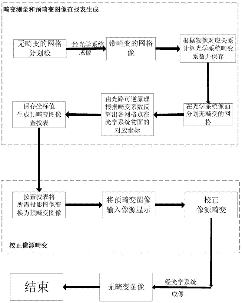
[0041] Such as figure 1 As shown, the system process is divided into three parts. The first part is the optical system distortion measurement and the pre-distortion image lookup table generation; the second part is the image source distortion correction; the third part is the corrected projection device.

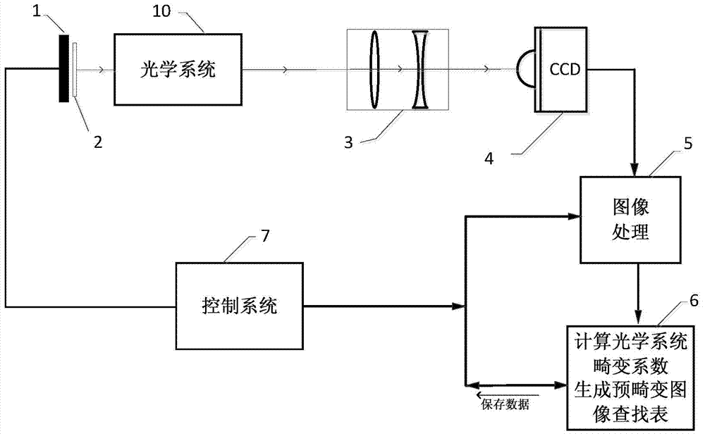
[0042] figure 2 for figure 1 Schematic diagram of the device in the first part of the system flow. Place the reticle 2 with the distortion-free grid on the object plane of the optical system 10, the shape of the reticle 2 is as follows image 3 As shown, it consists of several grids, the higher the correction accuracy required by the system, the more grids are div...


PUM


Abstract

The invention discloses a method for measuring and correcting distortion of a virtual reality displayer. The method includes the following steps that reticle imaging is carried out through an optical system to obtain a distortion grid image; a distortion coefficient of each grid is obtained through calculation according to the corresponding relationship between a vertex coordinate of the corresponding grid and a vertex coordinate of each distortion grid; non-distortion grids A are marked out on the distortion grid image, according to an optical path reversible principle, an object face of the optical system has distortion grids A' corresponding to the grids A, then vertex coordinates of the distortion grids A' are calculated by means of the distortion coefficients and the vertex coordinates of the grids A, and a coordinate look-up table is generated by means of the vertex coordinates of the distortion grids A'; an image to be projected is converted into a pre-distortion image by means of the coordinate look-up table, an image source is input, a pre-distortion image displayed by the image source is imaged, an imaging image is obtained, the imaging image is compared with the pre-distortion image, the image source is adjusted, and correcting of the image source is completed. The invention further discloses a device for measuring and correcting distortion of the virtual reality displayer.

Description

technical field [0001] The invention relates to the field of projection optical systems, in particular to a device and method for measuring and correcting distortion of a virtual display display. Background technique [0002] A virtual reality display is different from a general projector. It is a device that can directly project information such as text and images from an optical system to the human eye for imaging. The projected text and images are adjusted on an infinite plane, such as a head-up display (HUD) And the helmet-mounted display (HMD), which can integrate the external scene with the data of the display, so that people can conveniently and comfortably see the important information he needs without looking down. [0003] Virtual reality displays were originally used in military aircraft, and now they involve a wide range of applications. Virtual reality displays (HWD) with intelligent operating systems have begun to be commercialized, such as Google glasses; many...

Claims


Application Information

Patent Timeline
IPC IPC(8): G02B27/64
Inventor 郑臻荣李安夏新星吴懿思陈驰申俊飞张雅琴刘旭李海峰
Owner 深圳市安思疆科技有限公司
Learn More