Input undervoltage protecting circuit of switching power supply controller

A protection circuit and input undervoltage technology, which is applied to emergency protection circuit devices, electrical components, output power conversion devices, etc., can solve the problems of large resistance loss, poor resistance accuracy, and poor input undervoltage protection accuracy.

Active Publication Date: 2014-05-14
MORNSUN GUANGZHOU SCI & TECH
View PDF7 Cites 23 Cited by
  • Summary
  • Abstract
  • Description
  • Claims
  • Application Information

AI Technical Summary

Problems solved by technology

However, the input under-voltage protection and feed-forward compensation functions are separated from each other, which not only makes the peripheral resistors more, but also has a large loss through the resistors.
If the resistor R2 is built...

Method used


Image

  • Input undervoltage protecting circuit of switching power supply controller
  • Input undervoltage protecting circuit of switching power supply controller
  • Input undervoltage protecting circuit of switching power supply controller

Examples


Embodiment 1

[0052] like Figure 5 As shown, the first embodiment of the present invention includes:

[0053] The current detection circuit 101 includes a built-in current sampling resistor R2 in the controller, one end of which is connected to node A, the other end is grounded, and node A is connected to the VIN pin of the controller; an external resistor R1 of the controller is provided, and the resistor R1 One end is connected to the input voltage Vin of the switching power supply, and the other end is connected to the VIN pin of the controller, and the resistance value of the built-in resistor R2 is much smaller than the external resistor R1;

[0054] The reference voltage generating circuit 102 includes a controller built-in resistor R3 and a reference current source Iref, the reference current source Iref includes an operational amplifier amp2, an N-channel MOS transistor MN2 and a current mirror CM2, and the positive input terminal of the operational amplifier amp2 is connected to t...

Embodiment 2

[0076] like Image 6 As shown, it is the circuit diagram of the second embodiment of the present invention: compared with the first embodiment, the current detection circuit 201 of this embodiment also includes an electronic switch and a resistor R5, and the electronic switch includes a NOT gate not, an N-channel MOS transistor MN3, and a NOT gate The input end of not is the control end of the electronic switch, which is connected to the output end UVP of the comparator comp. The output end of the NOT gate is connected to the gate of the MOS transistor MN3, and one end of the resistor R5 is connected to the drain of MN3 and one end of the resistor R2. , the other end of the resistor R2 is connected to the node A, the source of the MOS transistor MN3 and the other end of the resistor R5 are connected to the ground; it can be seen that the resistor R5 and the resistor R2 are connected in series, and the electronic switch is equivalent to being connected in parallel at both ends o...
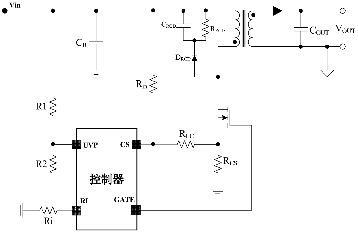
Embodiment 3

[0094] like Figure 7 As shown, it is a circuit diagram of Embodiment 3 of the present invention. Compared with the second embodiment, in this embodiment, the resistance R is increased in the feedforward compensation current generating circuit 303 LC , the output of the current mirror CM1 is connected by the built-in resistor R LC Connect to the controller CS pin.

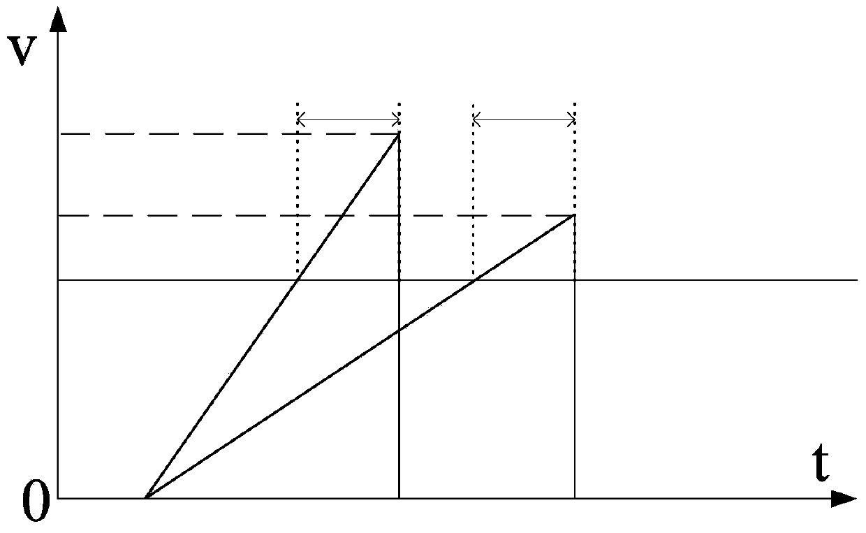
[0095] like figure 2 shown, the feedforward compensation is delayed by the controller T d time delay is generated, it causes R under high and low input voltages CS Terminal voltage difference V H -V L with respect to V OC is a small fraction of the ratio, through the feedforward current I com Built-in resistor R in 303 LC After forming the small voltage compensation, the ideal case can make V H -V L becomes zero. Although the internal resistance of the controller has poor accuracy, it is not possible to convert the V of all products H -V L becomes zero, but it can also be kept within the acceptable r...


PUM


Abstract

The invention provides an input undervoltage protecting circuit of a switching power supply controller. The input undervoltage protecting circuit of the switching power supply controller comprises a current detection circuit, a reference voltage generating circuit, an undervoltage protecting signal generating circuit and a pulse outputting control circuit. The current detection circuit comprises a controller internal resistor R2 and a controller external resistor R1, and the resistance value of the R2 is far smaller than that of the R1. The reference voltage generating circuit comprises an internal resistor R3 and a reference current source Iref, and the R3 and the R2 are resistors of the same type in the controller. The undervoltage protecting signal generating circuit comprises a comparator comp. A protecting point input voltage Vin(p) meets the formula (please see the formula in the specification). When the input voltage Vin of a switching power supply drops to be lower than the protecting point input voltage Vin(p), the output end UVP of the comparator comp generates undervoltage protecting signals to control the pulse outputting control circuit to cut off pulse output of GATE pins of the controller. According to the input undervoltage protecting circuit of the switching power supply controller, the peripheral circuits of the controller are simplified, the loss is small, meanwhile, the precision of input undervoltage protecting is high, and process bias is small. The invention further provides an input undervoltage protecting circuit with feed-forward compensation, the feed-forward compensation current Icom is in proportion to input voltages, the precision is high, and the process bias is small.

Description

technical field [0001] The invention relates to an input undervoltage protection circuit of a switching power supply controller, and relates to an input undervoltage protection circuit with feedforward compensation. Background technique [0002] like figure 1 Shown is the application circuit diagram of a typical switching power converter that does not include a feedforward compensation circuit (or called an overpower compensation circuit). The GATE pin is the drive output of the controller; the CS pin detects the voltage of the current sampling resistor RCS To determine the current flowing through the power MOS tube, it is often called the current loop; the operating frequency of the controller can be set by designing the resistance Ri from the RI pin to the "ground"; UVP is the input undervoltage protection function, at the minimum input voltage A protection voltage value is designed below. When the input voltage is lower than this value, the controller GATE stops outputti...

Claims


Application Information

Patent Timeline
IPC IPC(8): H02H7/12H02M1/00
Inventor 唐盛斌曾正球
Owner MORNSUN GUANGZHOU SCI & TECH
Why Eureka
Try Eureka