CT scanner, defocusing intensity measurement method of CT scanner and defocusing correction method of CT scanner

A scanner and intensity technology, which is applied in the field of defocus correction, can solve the problems of inconsistency in defocus radiation, inaccurate defocus correction coefficients, etc., and achieves the effects of strong adaptability, reduced data volume, and convenient operation.

Active Publication Date: 2014-05-21
SHANGHAI UNITED IMAGING HEALTHCARE
View PDF5 Cites 16 Cited by
  • Summary
  • Abstract
  • Description
  • Claims
  • Application Information

AI Technical Summary

Problems solved by technology

The disadvantage of the theoretical model calculation is that it may differ from the defocused radiation of the actual product, resulting in an inaccurate calculated defocus correction factor

Method used


Image

  • CT scanner, defocusing intensity measurement method of CT scanner and defocusing correction method of CT scanner
  • CT scanner, defocusing intensity measurement method of CT scanner and defocusing correction method of CT scanner
  • CT scanner, defocusing intensity measurement method of CT scanner and defocusing correction method of CT scanner

Examples


Embodiment Construction

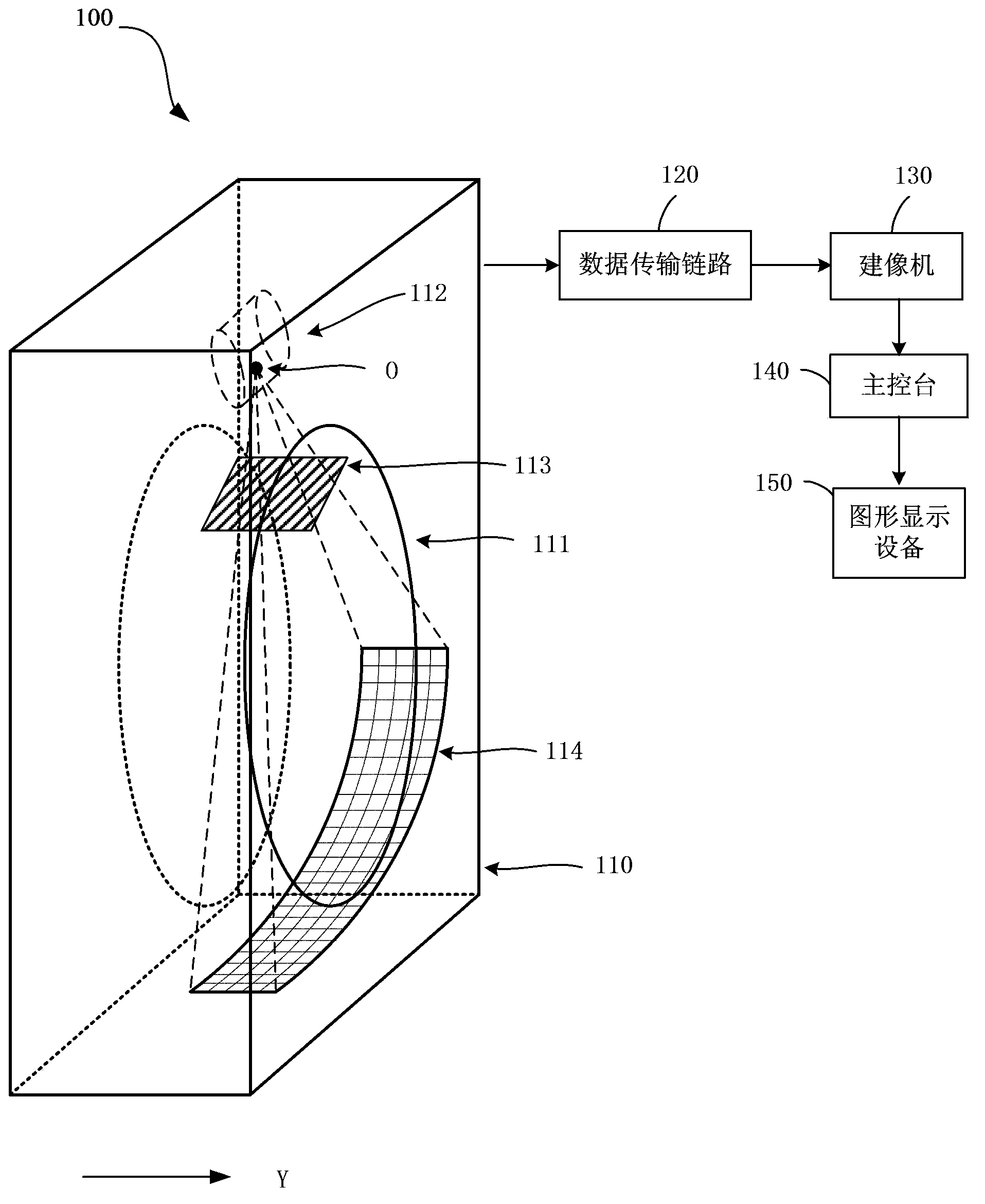
[0026] figure 1 A schematic diagram showing a CT scanner imaging system according to an embodiment of the present invention. refer to figure 1 As shown, CT scanner 100 includes a gantry 110 including a rotation mechanism having an aperture 111 . An X-ray tube 112 is provided on one side of the aperture 111 . The X-rays generated by the X-ray tube 112 are mainly emitted from the focal point O, and then directed to the object to be irradiated (such as a human body) located in the aperture 111 . The other side of the aperture 111 is provided with a detector array 114 for detecting the intensity of X-rays passing through the object to be irradiated. When the X-ray tube 112 and the detector array 114 are arranged on the rotating mechanism, when the rotating mechanism rotates, through the continuous irradiation of the X-ray tube 112 and the continuous detection of the detector array 114, various angles of the irradiated object can be obtained. radiation intensity.

[0027] In t...


PUM


Abstract

The invention relates to a CT scanner, a defocusing intensity measurement method of the CT scanner and a defocusing correction method of the CT scanner, and aims to provide an actual defocusing intensity measurement method and a defocusing correction method based on the actual defocusing intensity measurement method. The defocusing intensity measurement method includes the steps that a die body which can shield X-rays is placed in an aperture of a rack of the scanner; X-ray bulb tubes and a detector array of the scanner rotate around the rotating center of the rack of the scanner to execute rotating exposure scanning, and radiation intensity of the X-rays received by detectors can be accordingly weakened or enhanced due to the fact that the die body shields or retreats from the X-ray bulb tubes in every rotating circle; radiation intensity values are acquired from at least a part of the detectors at the preset sampling rate; eventually, defocusing intensity of the X-ray bulb tubes at the corresponding positions is calculated respectively according to the change of radiation intensity values of the detectors of adjacent sampling points when the die body gradually shields or retreats from the X-ray maximum radiation area of at least the part of the detectors, and then distribution of the defocusing intensity of the X-ray bulb tubes is acquired.

Description

technical field [0001] The invention relates to an electronic computer X-ray tomography scanner (abbreviated as a CT scanner), in particular to a method for measuring defocus intensity and a method for correcting defocus of the CT scanner. Background technique [0002] A CT scanner is a device that uses computer technology to reconstruct a tomographic image of a measured object to obtain a three-dimensional tomographic image. CT scanners use X-ray tubes to emit X-rays to the focal area, thereby focusing on the irradiated object (such as human organs). Defocus radiation is a phenomenon in which X-rays are radiated from areas other than the focus in the X-ray tube. It is caused by secondary electrons and field emission electrons bombarding areas other than the focus of the tube target area to generate X-rays. The defocusing phenomenon will lead to degradation of contrast or shadows at the edge of the illuminated object, affecting or even misleading doctors to make a diagnosis...

Claims


Application Information

Patent Timeline
Patent Type & Authority Applications(China)
IPC IPC(8): A61B6/03G01T1/29G06T11/00
CPCA61B6/032A61B6/4021A61B6/4291G01T1/2985G06T11/005
Inventor 季敏
Owner SHANGHAI UNITED IMAGING HEALTHCARE
Why Eureka
Try Eureka