Stacked spiral sludge dewatering machine

A sludge dewatering machine and stacking screw technology, which is applied in the direction of dehydration/drying/concentrated sludge treatment, etc., can solve the problems of sludge leakage, material cost of moving filter, and influence on treatment effect, etc.

Inactive Publication Date: 2014-05-21
陆小敏
View PDF2 Cites 11 Cited by
  • Summary
  • Abstract
  • Description
  • Claims
  • Application Information

AI Technical Summary

Problems solved by technology

[0004] There are still deficiencies in the above-mentioned patent applications and similar technical solutions: 1. The moving filter must have a circular hole that can pass through the swing rod. Since the swing rod is limited by the minimum deformation strength, the diameter of the swing rod is relatively large, and the dynamic filter The round hole on the filter must meet the penetration of the swing rod, so the moving filter is made of relatively expensive materials
2. The dynamic filter wears a lot during use. When replacing the dynamic fi

Method used


Image

  • Stacked spiral sludge dewatering machine
  • Stacked spiral sludge dewatering machine
  • Stacked spiral sludge dewatering machine

Examples


Embodiment Construction

[0014] Now, the present invention will be described in further detail in conjunction with the accompanying drawings and specific embodiments. These drawings are all simplified schematic diagrams, and only illustrate the basic structure of the present invention in a schematic manner, so they only reversely show the constructions related to the present invention.

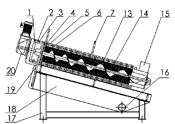
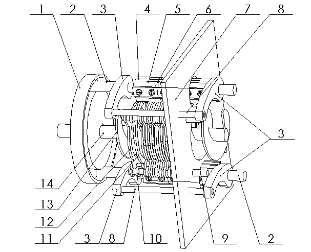
[0015] like Figure 1 to Figure 6 As shown, the stacked screw sludge dewatering machine includes an organic base 17, a water collection tank 18, a mud outlet 19, a reducer 20, a water inlet 15, a water outlet 16, an eccentric disk 1, an eccentric disk chute 101, and a swing shaft 2. Rocker arm 3, swing sleeve 4, fixed clip 5, fixed clip screw 6, support plate 7, rocker arm support shaft 8, fixed filter positioning shaft 9, fixed filter spacer 10, moving filter 11, fixed filter Filter disc 12, helical disc 13, helical shaft 14.

[0016] The base 17 is equipped with a plurality of support plates 7 arranged in paralle...


PUM


Abstract

The invention discloses a stacked spiral sludge dewatering machine. According to the invention, a screw shaft 14 rotates under the driving of a speed reducer 20, and at the same time, sludge with high water content enters into the periphery of the screw shaft from a water inlet 15; under the action of an upper screw panel 13 on the rotating screw shaft 14, the sludge with high water content gradually advances to a sludge outlet and is extruded; water droplets in the sludge are extruded out through gaps located between every adjacent fixed filter disc 12 and movable filter disc 11, then the water droplets fall into a water collecting tank 18 in a bracket and are discharged out of the dewatering machine through a drainage outlet 16; the dewatered sludge with low water content is gradually compacted, continues to move forward and is discharged out of the dewatering machine through a sludge outlet 19; the movable filter discs 11 rotate with the screw shaft 14 under the action of a transmission mechanism, each of the movable filter discs 11 swings up and down between two adjacent fixed filter discs 12, and the sludge among the movable filter discs 11 and the fixed filter discs 12 are cleaned so as to allow sewage to smoothly flow out from the gaps; each movable filter disc 11 is an elliptical ring composed by two arched structures and is fixed on a driving shaft sleeve by a fixing clamp, and if the movable filter disc is damaged, it only needs to remove the fixing clamp 5 for replacement of the damaged movable filter disc, which enables the machine to be easier to maintain.

Description

technical field [0001] The invention relates to a sludge dewatering device, in particular to a screw stacking sludge dewatering machine. Background technique [0002] At present, in the treatment and treatment of sewage, the selection and design of the sludge dewatering machine is extremely critical. Traditional sewage dewatering machines include plate and frame filter presses, belt filter presses, centrifugal filter presses, etc., but these pressure An obvious shortcoming of the filter machine is that the filter cloth and filter belt are prone to blockage or damage, or the energy consumption is large, and the operation is complicated, which affects the effect of sludge off-line in sewage treatment. In order to improve the effect of sewage sludge treatment, many enterprises and their technicians have carried out a lot of improvement and research on sewage dewatering devices, and developed a screw-stacked sludge dewatering machine. The design concept is composed of a fixed ri...

Claims


Application Information

Patent Timeline
IPC IPC(8): C02F11/12
Inventor 陆小敏
Owner 陆小敏
Why Eureka
Try Eureka